In the past two months I've continued working in Sketchup on a number of the projects outlined previously. None of them are, as of yet, finished. I was trying to take care of a few other things at the same time, but that cannot completely account for the lack of progress. After some consideration I've come to the conclusion that I've been trying to work on too many things at once. A distinct lack of focus has been a chronic problem of mine and this jumping from project to project has not helped the situation at all.
In order to get back on track, I'm going to work on one project at a time. The first order of business is getting back to the interior of the 3200-series cars. The last time I discussed this, I had recently gotten the prototype seat back from Shapeways and was relatively pleased with the result. That didn't last. As I discussed in that post, I left the possibility open that I might try my hand at making the scoop in the seats. Lo and belold! I did just that. (This is the hazard of never being satisfied with your own work.)
They aren't "perfect," but I am satisfied with how they look. (For now.) I haven't printed this design yet, although it did pass Shapeways' file initial and wall thickness checks when uploaded. That's good enough for me and I've gone ahead and begun designing the different types of seats found in the 3200-series. These are (from memory) as follows:
- Single seat with handhold (pole on left)
- Single seat with handhold (pole on right)
- Single seat without handhold
- Double seat with handhold
- Double seat with handhold and ventilation box
- Double seat without handhold
- Wheelchair position double seat (flips up)
- Longitudinal double seat with windbreak on left
- Longitudinal double seat with windbreak on right

Shapeways digital preview of some of the pieces to be made. The scoops are more evident in this rendering than they would be in a screenshot from Google Sketchup.
The problem with simply printing the chairs is that a fair number of them are not self-supporting. They are (naturally) small and somewhat fragile. Trying to accurately mount something of this type to the floor of a model sounds like a chore and a half. I've thought about this for some time and eventually came up with something I'm willing to try.
The obvious answer is to print them as part of the car floor and be done with it. Unfortunately, this would be expensive to do (still earning vet tech wages) and the product is too large to be produced by the Frosted Ultra Detail printers. (The details are too fine to be printed in anything else.) My solution is a sort of compromise on this idea. I plan on dividing the car into three sections (front, middle rear) and designing the interiors in these sets. Each set will have all of its "furniture" (chairs, windbreaks, door pockets, etc.) created together and mounted onto a thin "surface floor." The three sections would then be placed end to end and mounted onto the real car floor (made of an inexpensive, but durable, material) and slid into the car body as one piece. Doing it this way solves the problem of mounting the chairs properly (without damaging them!), positioning them correctly, and also will allow me to make the grooves in the floor fairly easily. The grooves can also help to hide the separation lines between the three segments. We'll have to see how well this works and how expensive it turns out to be...
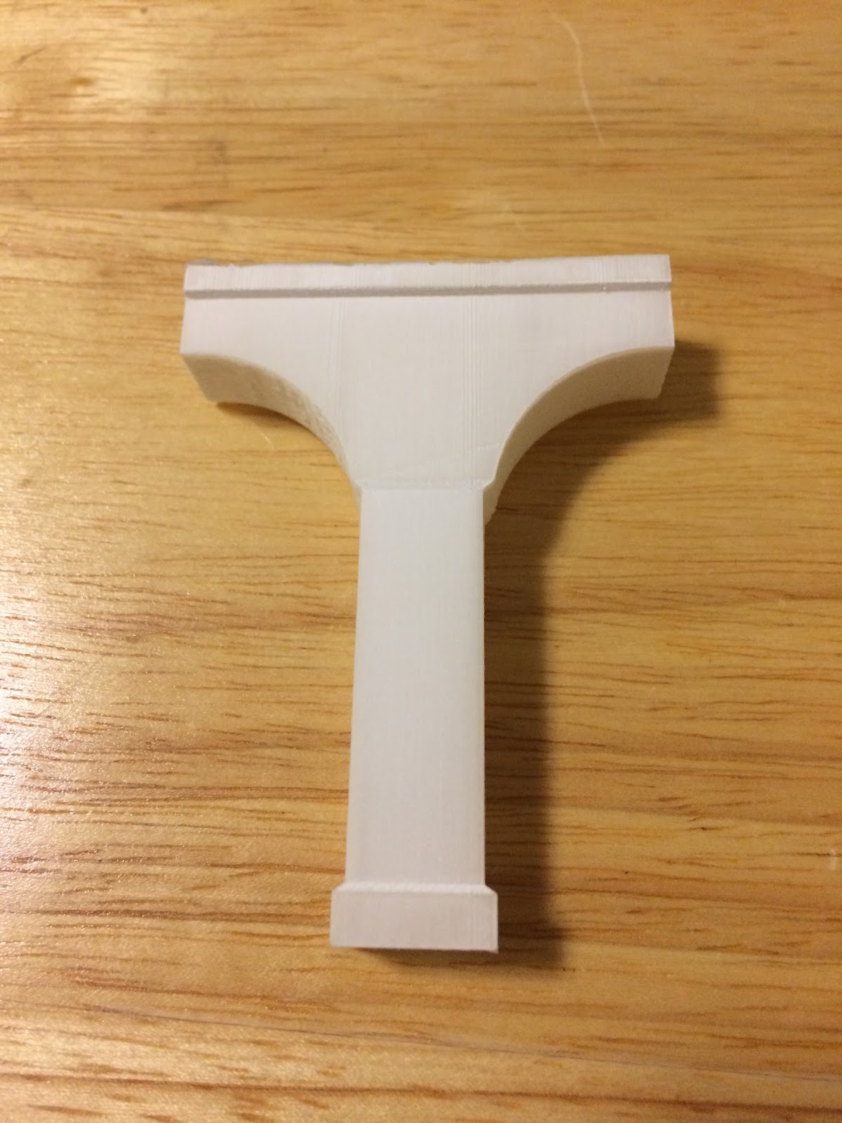
There has been a definite success with the printing. I sent off the updated version of the snowplow frames and received the finished product days later. These are a resounding success. I just have to fit them with the blades (to be made from index cards) and paint them.

These are remarkably crappy photos, but they do illustrate the point. This is a pair of snowplow frames, held back to back by sprues. They have a good amount of detail (which probably won't even be seen) and are decently strong. They're also reasonably flexible so they shouldn't break too easily.
I also have some new acquisitions to report: CA&E car 500 and a section of the Lake Street "L" structure. Both of these come to the Dunsel Line via the Chicago, Wheaton & Western (my father). He's beginning to focus on some other things and has come to the conclusion that he won't be doing anything with either of these, so he gave them to me.
The 500 (which could also be built into a North Shore Line 350-series streetcar—yeah right) is from a kit produced by Greg King. Currently it is completely unassembled, although it did come with a Q car power and trailer truck set. The downside is that the power truck is only set up for overhead operation. This will pose a slight problem as my (eventual) layout will be two rail, but for the time being it doesn't matter. (I'll probably also change out the power truck later.)
The Lake Street "L" structure is from a portion of the line with provision for only two tracks and the majority of support columns in the street and not anchored at the curb. The structure is somewhat old and slightly brittle. When removing it from my father's basement, I accidentally slightly tapped one of the columns against a wall and it broke off. (Apparently this has happened before.) I believe it is still structurally sound, so I'll fix it and post photos of it at a later date.