Showing posts with label Yellow Line. Show all posts

Friday, August 14, 2015

Pantographs and Trolley Beams

Strap in! It’s a long one.


Since May I’ve made some headway on a number of projects. 3D modeling continues as always and on July 9, I received the first print of the experimental roof walks for the 3200 series cars. The walks in question are only the rear half, the portion that is only half-width. This was done as a cost saving measure for the test article.

The plan was to see how these came out and then work on and produce the front half which supported the pantograph. The two sections will line up and be glued together to form one complete piece. Instead of attempting to match the curve of the MTH roofs, I made the support brackets slightly longer than needed. Once glued together, I’ll place a piece of sandpaper on the roof and then gently rub the roof walks back and forth on top until they conform to the shape of the roof.

Unfortunately, after looking at the piece and being wholly satisfied with it, I began work on the forward portion only to discover that it would be visibly too wide for the car. To fix it, I needed to reduce the gaps between the horizontal members by 0.2mm each. Since the rear portion and the front portion have to line up, this meant that the rear portion needed to be narrowed as well, rendering the original one unusable.

I was able to make the rather tedious corrections relatively quickly and sent off for an updated version. Thankfully Shapeways was having a short term deal where shipping is free.

The narrowed rear portion of the roof walks arrived on the 16th and it definitely looks better than the original. The downside is that this was the first piece that I’ve gotten with some kind of a printing error. It arrived with a globule of “white stuff” which went across and between the slats in one section.

This didn’t come off while soaking in Bestine but did come off afterward after being cleaned with an old toothbrush under running water. Some of the slats were damaged (either in production or during cleaning—impossible to tell which) and from certain angles this shows. This end also has a strong odor of cherry syrup, which is highly unusual since 1) none of the other pieces have had this smell and 2) I can actually smell this with my barely functional nose! (The fact that I can smell it really attests to the strength of the smell.)

Otherwise, the piece came out well.
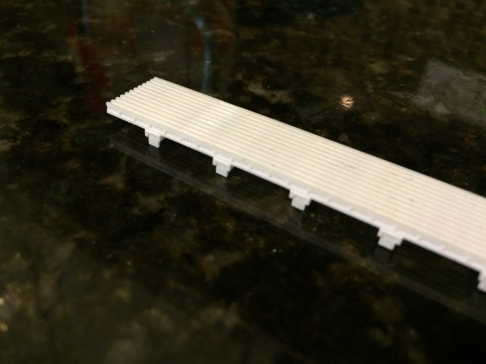
The damaged area is slightly visible from this angle. It is between the first and second supports on the left. In removing it, some of the top portion of the walk was damaged.

The original is at top. The newer one has been soaked in Bestine, giving a clear demonstration of what the agent does to Frosted Ultra Detail. Again, damage is visible here.

Tying in with the roof boards, my father and I took a trip out to the Illinois Railway Museum on Wednesday, July 8. While there, I was able to locate the pantographs from the 3200s and get some preliminary measurements. Now that I know where they are, I’ll be sure to acquire a very detailed set of measurements to be able to build the correct ones myself.

Progress has also been made on a new set of trolley beams for the same cars. I’m still working on perfecting the design of the third rail shoes themselves, but the equipment supporting the shoe has been designed and printed. This is a test to see how Frosted Ultra Detail handles separate-but-interlocking parts. (I would feel immensely satisfied if I could manage to produce dangling third rail shoes that could also glide on top of a rail.) If this fails, I can at least manufacture a set of trolley beams for the 3200s that don’t have provision for sleet scrapers on the rear trucks, as is prototypical.

The test piece also arrived on the same day as the narrowed roof walks. The two loops which hang down and connect to the third rail shoe do dangle, but not as freely as I’d hoped. Soaking them in a bath of Bestine did help, as did working them a bit, but they still don’t swing completely freely. I’m hoping there’s some kind of lubricant I can try to make them work better. I’d rather not resize the parts to improve “functionality” as areas on this piece are already pushing the limits of Frosted Ultra Detail in terms of minimum width and also because this would alter the look of the piece.

Perhaps it’ll work better once the shoe itself is added. Fingers crossed.

I actually printed this piece in Frosted Extreme Detail (which is the same material as FUD, but printed with thinner layers). The difference in cost for such a small piece ended up being 10¢ and I figured a dime was worth the expense of finding out what the big deal was.

Ultimately I don’t see too much of a difference and it certainly doesn’t seem to be worth the extra cost for larger pieces.


Additionally, I purchased a pair of Japanese pantographs from the East Gary Car Company. These pans are supposed to be junk, but as it’s the shoes I’m interested in, that doesn’t matter. I am fortunate enough to know someone who has a small, but overfilled workshop. He had a spare rotary tool (Ryobi, not Dremmel) that he didn’t want taking up space and he gave it to me. (One tool down that I don’t have to purchase!) Using this, I have already cut apart the shoes on one of the pans. (So far no complaints about the Ryobi.) These shoes (of which there will be four in total) will be for the 1-50 and 5000 series trolley pans. I still need to gather more information on the trolley pans before continuing much further down this road.

One of the big things holding me back on the 1-50 (car 2) and the 5000 (car 52) is my lack of a soldering iron. I’ll need this not only for the construction of the trolley pans, but also to remove the existing roof boards on both cars. I’m already stretching money a bit so this isn’t something I’ll be purchasing in the immediate future.

A tase of things to come

Still, progress continues. The middle section of car 52 doesn’t (and never did) have roof boards since there never was any trolley equipment located there. This makes the middle section an ideal place to start. I’ll prime this section as soon as possible.

The wheels on the 52 are another issue. As built, the 5000 series cars were equipped with resilient wheels. By the time the cars were assigned to the Skokie Swift and rebuilt, these wheels had been replaced with standard equipment.

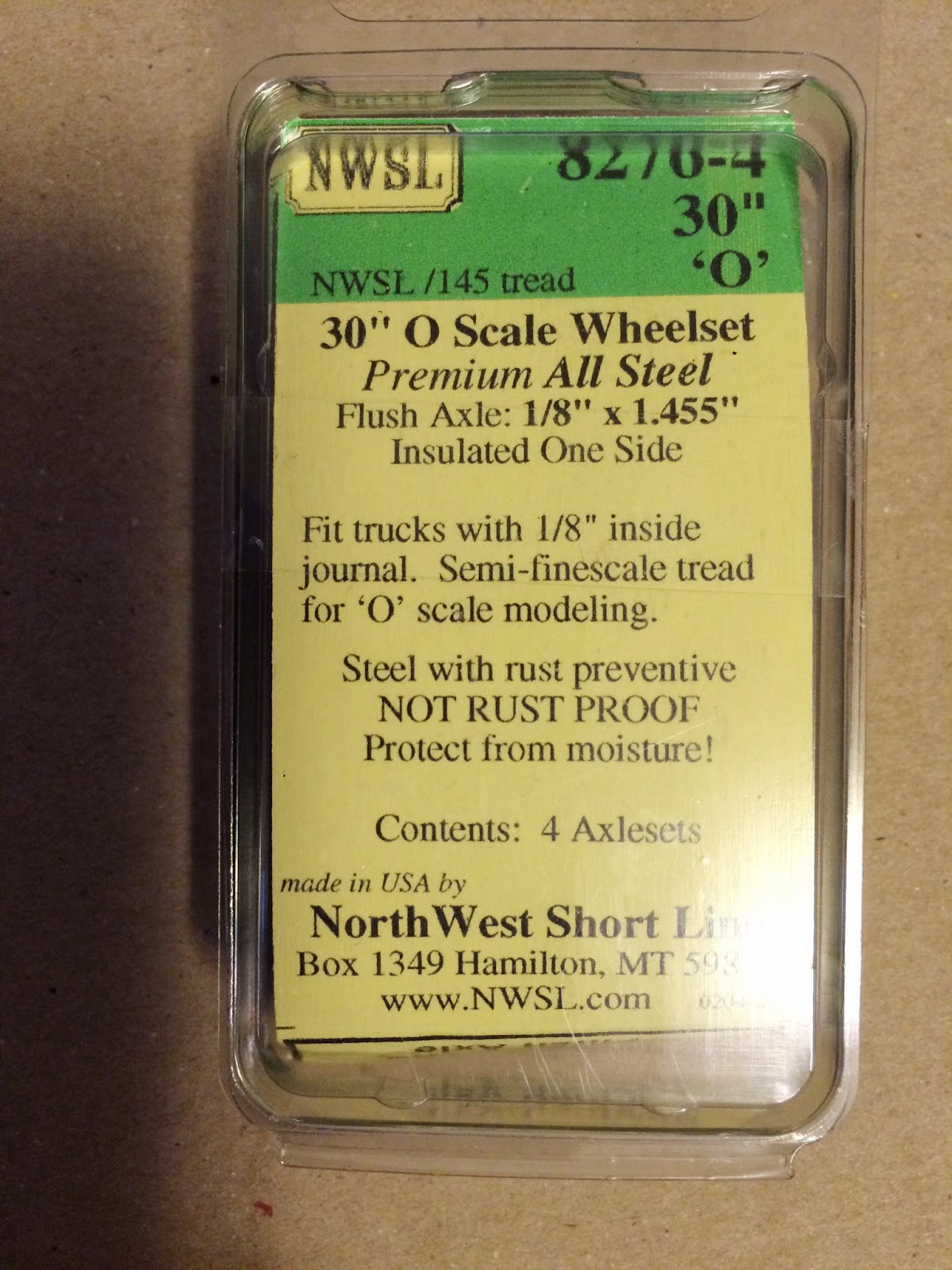
The trucks supplied with the car are correct in appearance (they’re actually a fair sight better than the CTA 6000/1-50 Clark B3 trucks from Q Car) so I’ll be keeping these and replacing the resilient wheels currently on the model with “regular” 26” flush wheels from NorthWest Short Line. I haven’t decided on what to do with the power trucks yet. (I’m not even sure that the wheels are insulated. I have a strong doubt that they are.)

Wednesday, May 13, 2015

Step right up

The steps arrived from Shapweays a few days ago and (in spite of my initial misgivings) I’m completely satisfied with the results. They don’t look bulky at all and should look very good once applied to the cars.

The one downside to the 3D printing process at Shapeways is that they don’t give the designer control over the print orientation. This is of vital importance to the final product as the print orientation determines which face will ultimately show the layers of the printing process. With control over this, a designer could specify a particular face to be “up” or “down” in the process and thus eliminate printing lines on surfaces that are intended to be seen.

Unfortunately, Shapeways will not relinquish this control to individual designers as they print orders on a tray en masse and each part on that tray is supposedly oriented in a position to optimize use of the wax support material for production. (This waxy support material is the substance that’s usually stuck to parts once they come from the printer.)

I’m not sure how this was “optimized” for the steps as they seem to have been printed on a diagonal. (Picture a cube balancing on one edge instead of sitting on a side.) This has left some very small (but still visible) jagged edges that I will have to very carefully sand smooth. This was my fourth printed piece and so far none of them have returned with any visible amounts of residual wax (this may be due in part to the fact that all of my pieces to date have been rather small) but I went through the process of wax removal anyway just to be safe for priming and painting.

The tried and true method for dewaxing Frosted Ultra Detail is to soak the part in a bath of Bestine. Bestine is a solvent and thinner for rubber cement. It can be purchased online or at art supply stores. In the Chicago area both Blick’s and Utrecht carry it. I used an old glass jar to facilitate the process.

How they appeared prior to wax removal. (It was exceptionally difficult to get these even remotely in focus.)

The imaginary minced garlic in this container contains chemicals known to the state of California to cause cancer.

I submerged the set in the Bestine for ten minutes before returning the solvent back to its container. Visibly there was no outward change that any wax had been removed, but the surfaces of the piece had turned white. This is normal for the chemical wax removal process.

Some of the jagged edges can be seen here.

After setting the piece on a paper towel to dry, I carefully separated each set of steps from the sprues. In order to save on cost, I went the minimal approach and spaced each piece very closely to keep the amount of material used as low as possible. The downside to this was that in some cases there wasn’t much space available to cut. Fortunately they all separated cleanly. The part that really had me worried was cutting the remaining sprue pieces off since the ladders are angled and in many cases could not be put on their flat sides to make the necessary cuts. Frosted Ultra Detail, it turns out, is flexible enough and strong enough. Even when printed at its minimums, each part took the cuts with no damage. This was followed by a bit of light sanding with 800 grit sand paper and they were ready to prime.

After separation, but before sprue removal.

Since ventilation in my house isn’t generally good (and by “generally” I mean ever) and since I have several small birds that would be extremely susceptible to fumes, all of this has to be done outside. This also means that work is dependent on the weather. I liberated a cardboard box from my job to serve as a hood. Because these pieces are so small and light, a gentle zephyr could take them away. To solve this they’ll be stuck to loops of tape which will be taped to the back of the box. Once the weather cooperates they’ll be primed.

No, not this kind of Zephyr.

Since Memorial Day is coming up, my family and I will be taking a trek out to the Illinois Railway Museum and I’ll finally be able to get the remaining measurements I need for the 2200 series and hopefully I’ll have time to take a crack at the 2400 series. (With my luck they’ll both be in operation and I won’t get at them.) I do have a new “secret” project that this visit may certainly help. Keep an eye out for it!

Thursday, May 7, 2015

April on the Dunsel Line

As predicted, April was a slow one on the Dunsel Line. There were no new purchases even though some were available. A pair of CA&E 450s was out there, but I passed these up. It’s just as well. I’ve already got two North Shore trains to work on in addition to the Skokie Swift pieces. Makes sense to at least try to finish some of this stuff, right?

As planned, I went ahead with more 3D modeling projects for the 3200 series cars. Unfortunately the Form 5 coupler is still not complete. My own attention to detail is really getting the better of me here. At this point I’m primarily stuck on one specific section of this model and lately I haven’t wanted to think about it so I’ve been avoiding it. (Not exactly an attitude that’s conducive for getting things done.)

Another project which I have been modeling is the steps for the 3200s. For whatever reason, when MTH made these cars, they didn’t include the steps. I suppose this stemmed from the same issue with getting the underbody equipment totally wrong. (Thankfully, when they produced the 6200 series, they fixed both of those issues.)

This is actually been a project that I’ve been working on since my last trip to IRM. For such a simple model I’ve really spent far too much time reworking things to get them right. Early on I kept getting holes in the model that refused to be patched and I hadn’t yet discovered the “intersect with selection” method which is necessary for making the angled portions of the side steps.

This method involves drawing a shape (in this case it was a rectangle) shifted to the appropriate angle and then moved to intersect the part of the model that needed to be “cut” at an angle. Once in place, both parts (the shape and the model) were selected and right clicked. This brings up a menu from which intersect is an option. It has two suboptions: “intersect with model” and “intersect with selection.” Intersection basically finds all the points of intersection between the two pieces and draws definitive lines at these points and incorporates them. From here the rest is easy; all that’s left is deleting all the unnecessary parts.

I wasn’t satisfied with how they looked on my computer in Sketchup or in the Shapeways render. They looked too thick to be right. I had to remind myself that the sides came out to be 0.6mm thick, the smallest workable size in Frosted Ultra Detail and this was thin enough to look good on the snowplows. Despite my misgivings I had them printed anyway and they arrived today. I am extremely pleased with how they turned out. This should serve as a reminder that I really should just take a deep breath and relax. (But it won’t.)

Speaking of the snowplows, I have made a discovery: they’re too wide! How frustrating. The angled bars at the top along side of the framing are supposed to fit neatly within the gap under the anticlimber. Unfortunately, the model plows are about 1mm too wide to fit within this space.

Attempting to rescale the snowplows didn’t work either. (Unlike the steps, the snowplows weren’t drawn full size and then scaled down. I mathematically scaled down the dimensions and then rounded these numbers to fit within the Frosted Ultra Detail guidelines.) In order to get them right I’ll have to redraw them. (All dimensions save for the width are correct, so cutting out 1mm from the center won’t work as this will decrease the distance the snowplows protrude from the ends of the frames.)

I’m not looking forward to this, but I’ll make the necessary modifications because it will gnaw on me until it’s right.

Another project I’ve been working on is the full-width cab partition in its closed state. (I’ll also be making one in the open state; that is, one where only the motorman’s position is closed off to the public.) This is nearly ready and is publicly visible in my list of designs on Shapeways. I’m still not satisfied with a few details at the moment. Something looks off about the position of the windows in relation to the “bar” above the cab door. I’m going to take some more measurements before finally sending this one out to be printed.

In addition to checking and/or correcting the window heights, the door handle also has to be finished.

The wheels which I ordered from Northwest Short Line arrived and—as expected—look good. Now I just need to build a pair of trailer trucks for them. But since these have arrived, I found myself wondering about the trucks I ordered for the Skokie Valley train. I placed the order for these in early to mid January and still haven’t received them. Apparently they’re still waiting on parts, but at least the order wasn’t lost!

These aren't 100% correct, but the difference between 30" in 1:48 and 28" in 1:45.2 is so close that getting the commercially available set is close enough.

A side view of the wheels.

Tuesday, March 31, 2015

March in Review

Let’s get straight to the point; I spent a lot of money this month. Even though I’d planned on spending a good deal of money on models this month, my actual total greatly exceeds my anticipation (and this doesn’t even cover routine things like food and bills). I had a number of other projects (not model related) that also cost more than expected, so April will almost certainly be a very quiet month around here.

With that said, it seems like a good time to stop and reflect on a very expensive (but good) month. March is the month of the Chicago O Scale Meet (also known as the March Meet) and associated open houses at various trolley layouts. Preparation for these two prompted me to get back in gear and begin working on the 3D model of CTA’s form 5 coupler.

Ultimately this design wasn’t finalized in time for the open houses (I was only able to attend one) and the design work is still ongoing. The continuation of this project should be a nice one to carry on into April.

Before the meet I was able to get my hands on a Clouser North Shore steel coach. Although it did not come with trucks, I did get a good deal on it and am very happy with my purchase. The following week was the March Meet and there I bought a brass North Shore 170-182 series coach. Acquisition of this car has enabled me to outline and define my projects for the North Shore Line. I’d already decided on modeling the North Shore circa 1952/1953 (the same years for the CA&E) and the addition of these two older steel cars has led me to separate my efforts into the creation of two trains: Chicago-Milwaukee via Skokie Valley (the combine and upper 700) and a Chicago-Waukegan Shore Line train (the “older” coaches).

I have already ordered a motor truck set that would be applicable to either car on the Skokie Valley train, so I’m waiting for that to arrive. I’ll have to construct a test track pretty soon, which I suppose will be the very beginnings of my layout.

Also at the O Scale Meet I bought a pair of pantographs to turn into sausage. The shoes on these will be cut apart, to produce four “single” pantograph shoes. Each of these will be mounted at the end of a pair of four-spring horizontal trolley poles. I still need to buy a total of eight trolley poles for car 2 (the 1-50) and car 52 (the 5000) to make this. As a result of... overspending... I probably won’t begin this phase of that project in April.

After the March Meet I went back and made complete 3D models of the 3200-series snowplows. After increasing the size of the nuts so that they would register at Shapeways, these were sent off to the printer. They arrived on Monday and I am extremely pleased with the results. I’ve already made these available via the Ravenston Car Company at Shapeways. (Shameless self promotion!)

In continuing work on the 3200s, I ordered a set of wheels from NorthWest Short Line. I had planned on mounting these inside of cheap, temporary trucks (shop trucks) but I’ve abandoned this idea in favor of 3D printing my own set of “test trucks” which will enable me to try a few things out and see how well this will actually work. Unfortunately, 30” wheels are on backorder for about a month, so this particular project will probably have to wait for a while. In the meantime I’ll see if I can gather some pictures of the Duewag trucks with which the cars are equipped.

I know someone who claims (strong emphasis on “claims”) that he has access to equipment to make metal casts and, if all goes well, I should be able to make molds of the 3D prints and produce a series of metal trucks.

Even after the end of the March Meet March continued to be a money spender! I found another brass 1-50 series car and didn’t hesitate to grab it. To model the four basic iterations of Skokie Swift equipment as planned, I need a total of three of these cars: one as for a single-unit 1-50 and two for a double-unit 60. I now have two.

My first 1-50 has a dent on one end which I should be able to hammer and fill back into shape. Regardless of how well this turns out, the original (dented) 1-50 will now be used as part of the 60 pair with the dented face being positioned between the cars to minimize its visibility. The new car will now be the single and will get the CTA designed trolley-pans.

I also started work on a 3D model of the resistor grids for the 3200 series. This model uses measurements taken from the pair of 2400-series cars at the Illinois Railway Museum. There are subtle differences between the 2400 and 3200-series equipment that I have to account for and I’m currently working with the design to get it right.

The benefit of creating this model in full scale and then reducing it is that it can effectively be used to create specific models for the 2400, 2600, and 3200-series cars with only minor variations in each and scaled appropriately to 1:45 for the 3200s and to 1:48 for my planned 2400s and 2600s.

The 2200-series cars (which I have already started designing) used a resistor set that was substantially different than those used on the later cars. During my last trip out to IRM, I didn’t take underbody measurements for the 2200s, so I won’t be able to continue work on that particular set until I make another trip out to Union.

Finally (my wallet has its fingers crossed that this really is finally) I found a power truck set that would be appropriate for either car in the Skokie Valley train. It matches the truck I ordered from NorthWest Short Line, although at present I don’t know if the motors are Magic Carpet IIs or IIIs. The main impetus for getting this truck was the fact that I was able to get it for a substantially lower price than normal.

Moving forward into April my projects are most likely going to be all 3D modeling as this can be done at no cost. I plan to finish the form 5 coupler, work out the kinks with the resistors, and begin creation of an underbody set for a 2400-series pair (since I have photos and measurements on hand for that). I’ll also be continuing to fabricate the replacement car floor for the second 3200-series car.

Friday, March 20, 2015

Back to Business: Snowplows Again

The Dunsel Line shops are predominantly (literally) a virtual operation at this point. Naturally, most work done there is done on the computer.

I’ve decided to take a brief break from designing the Form 5 coupler and go back to an earlier project: the Q scale (1:45) snowplows for the 3200s. Previously I had stated that I would produce the snowplow “blades” from cardstock and glue them to the 3D printed frames I’d produced. I’ve decided to scratch that idea and just have the whole thing printed as a complete piece. This opens up the product for anyone else who would desire to reequip their MTH 3200s and/or 2-rail them.

On Sunday I went back in and added the blades and accompanying parts.

I think they look pretty good. And, better yet, they pass the tests for Frosted Ultra Detail. They’re ready to print!

Not so fast. Wait a minute… Where are the nuts holding the blade to the frame? They’re in my 3D model and they’re of a size that’s printable in FUD.

This is Shapeways' preview image. As you can see, the nuts pictured in the 3D model are not present here.

This is really starting to piss me off. This is the third time parts have gone missing when I've uploaded a model to Shapeways. (I am not blaming Shapeways for this error.) Somewhere in the conversion from the .skp file to .dae (done in Windows via "File" > "Export" > "3D model...") parts go missing and I still can't figure out why.

I'll delay printing until I solve this constant issue.

But in other, non-virtual, news I've begun fabrication of the car floors for the 3200s. I'm using 0.060" Evergreen styrene.

The holes drilled in the floor mark where the trucks will be mounted. If you have a sharp eye you've noticed that one of the holes doesn't line up with the line drawn down the length of the car body. This is not an error. The hole is correct, the line is off on that end by about 1/16". Since I won't be reusing the trucks the cars came with, I'll have to build my own and I'll be purchasing a set of wheels from NorthWest Short Line soon.

The 3200s are equipped with 28 inch wheels. In 1:45 scale, this comes out to a diameter of 0.622 real inches. 30 inches in O scale comes out to 0.625 real inches. The 30 inch wheels will therefore be 0.003 inches too wide, but I'm willing to settle. Once I get the wheels, I'll acquire a pair of cheap trucks for the floors to sit on while work progresses.

Sunday, December 7, 2014

Time to Focus

In the past two months I've continued working in Sketchup on a number of the projects outlined previously. None of them are, as of yet, finished. I was trying to take care of a few other things at the same time, but that cannot completely account for the lack of progress. After some consideration I've come to the conclusion that I've been trying to work on too many things at once. A distinct lack of focus has been a chronic problem of mine and this jumping from project to project has not helped the situation at all.

In order to get back on track, I'm going to work on one project at a time. The first order of business is getting back to the interior of the 3200-series cars. The last time I discussed this, I had recently gotten the prototype seat back from Shapeways and was relatively pleased with the result. That didn't last. As I discussed in that post, I left the possibility open that I might try my hand at making the scoop in the seats. Lo and belold! I did just that. (This is the hazard of never being satisfied with your own work.)

They aren't "perfect," but I am satisfied with how they look. (For now.) I haven't printed this design yet, although it did pass Shapeways' file initial and wall thickness checks when uploaded. That's good enough for me and I've gone ahead and begun designing the different types of seats found in the 3200-series. These are (from memory) as follows:

  • Single seat with handhold (pole on left)
  • Single seat with handhold (pole on right)
  • Single seat without handhold
  • Double seat with handhold
  • Double seat with handhold and ventilation box
  • Double seat without handhold
  • Wheelchair position double seat (flips up)
  • Longitudinal double seat with windbreak on left
  • Longitudinal double seat with windbreak on right

Shapeways digital preview of some of the pieces to be made. The scoops are more evident in this rendering than they would be in a screenshot from Google Sketchup.

The problem with simply printing the chairs is that a fair number of them are not self-supporting. They are (naturally) small and somewhat fragile. Trying to accurately mount something of this type to the floor of a model sounds like a chore and a half. I've thought about this for some time and eventually came up with something I'm willing to try.

The obvious answer is to print them as part of the car floor and be done with it. Unfortunately, this would be expensive to do (still earning vet tech wages) and the product is too large to be produced by the Frosted Ultra Detail printers. (The details are too fine to be printed in anything else.) My solution is a sort of compromise on this idea. I plan on dividing the car into three sections (front, middle rear) and designing the interiors in these sets. Each set will have all of its "furniture" (chairs, windbreaks, door pockets, etc.) created together and mounted onto a thin "surface floor." The three sections would then be placed end to end and mounted onto the real car floor (made of an inexpensive, but durable, material) and slid into the car body as one piece. Doing it this way solves the problem of mounting the chairs properly (without damaging them!), positioning them correctly, and also will allow me to make the grooves in the floor fairly easily. The grooves can also help to hide the separation lines between the three segments. We'll have to see how well this works and how expensive it turns out to be...

There has been a definite success with the printing. I sent off the updated version of the snowplow frames and received the finished product days later. These are a resounding success. I just have to fit them with the blades (to be made from index cards) and paint them.

These are remarkably crappy photos, but they do illustrate the point. This is a pair of snowplow frames, held back to back by sprues. They have a good amount of detail (which probably won't even be seen) and are decently strong. They're also reasonably flexible so they shouldn't break too easily.

I also have some new acquisitions to report: CA&E car 500 and a section of the Lake Street "L" structure. Both of these come to the Dunsel Line via the Chicago, Wheaton & Western (my father). He's beginning to focus on some other things and has come to the conclusion that he won't be doing anything with either of these, so he gave them to me.

The 500 (which could also be built into a North Shore Line 350-series streetcar—yeah right) is from a kit produced by Greg King. Currently it is completely unassembled, although it did come with a Q car power and trailer truck set. The downside is that the power truck is only set up for overhead operation. This will pose a slight problem as my (eventual) layout will be two rail, but for the time being it doesn't matter. (I'll probably also change out the power truck later.)

The Lake Street "L" structure is from a portion of the line with provision for only two tracks and the majority of support columns in the street and not anchored at the curb. The structure is somewhat old and slightly brittle. When removing it from my father's basement, I accidentally slightly tapped one of the columns against a wall and it broke off. (Apparently this has happened before.) I believe it is still structurally sound, so I'll fix it and post photos of it at a later date.

Sunday, September 21, 2014

Success on Two Fronts

Okay, so this update is long overdue. In the intervening weeks I have had some successes with my models and my "layout." I have come to the decision (largely in part because of the purchase of the 2000-series cars) that the Dunsel Line will not be a traditional trolley layout. It will be a two-rail layout equipped with dummy third rail. This will allow operation of CA&E, North Shore, and "L" equipment even if the cars (such as the 2000s) are not equipped with trolley poles or pantographs. This will necessitate the pole- or pan-equipped cars to built to accommodate two modes of running, as they should be. This does come with a downside.

Prototypical placement of the third rail on the "L" has the top of the third rail 6½ inches above the top of the running rail and 20-1/8 inches from the inside edge of the running rail to the center line of the third rail. Contact with the third rail is made by a metal shoe (or a paddle in the case of very early AE&C cars). Contact with the third rail is made by gravity: the shoe naturally hangs and then glides across the surface of the rail when present. The problem here is that most on models, the shoe has been made in the free hanging or "down" position. This is fine for trolley operation as when under wire, the shoes should hang freely. With prototypical third rail placement, the shoe now hangs too low for operation. The MTH "L" cars have the shoe in the up or "on rail" position. This works well for prototypical placement unless the third rail is on the non visible side of the model or at gaps. In these situations the shoe isn't hanging when it should be.

A trolley beam on a St. Petersburg 2000-series car. The shoe is depicted as hanging free. This would collide with a prototypically placed third rail.

MTH made the shoe in the "on rail" position.

There are three ways to work this problem. The first is to use the commercially available trolley beams in the free hanging position and adapt the height of the third rail accordingly. The other is to use the on rail position and place the third rail according to where it will be seen by the viewer. I'm not entirely satisfied by either of these options.

The third option is, if at all possible, is to create a trolley beam with a third rail shoe that functions like the prototype so that it can glide or dangle as need be. I'm a neurotic freak so this sounds extremely satisfying. I had this idea in the past, but dismissed it due to my inability to construct such a small thing effectively. But now I can have things 3D printed! And according to the specifications on Shapeways' site, many materials do allow for moving parts if proper clearance is built into the design. Looks like I've got a new project...

Granted, this won't take into account the placement in the third rail given the difference in scales (1/48 vs. the 1/45 for the MTH cars) but I'll just have to live with it.

This actually leads to the first of my successes. The prototype seat for the 3200-series cars arrived from Shapeways on Monday and I’m pleased with the results.

This took far longer than I’d expected and was also fraught with no small amount of frustration. The first problem was getting the angle of the seat back to my own satisfaction (picture a weirdo riding the Ravenswood messing around with perfectly normal seats with a protractor and a crude, improvised plumb bob). The next (and far more frustrating) bit was to create the handhold on the back of the seat.

I was very much relieved to discover that the handholds on the 3200s are much simpler than their counterparts on the 22-, 24-, and 2600-series cars. Until I tried to produce them, that is. The process involves making an appropriately sized circle which will be the “pipe” in question and then drawing a curved line representing the path of the pipe. In this case, the path went up from the circle, curved to one side, continued horizontally, and then curved down to the same height at which it started. Once that path is created and placed on the appropriate plane (another interesting quest in of itself) and positioned with the start at the center of the circle, the “follow me tool” is used to extrude the circle along the specified path. Simple. Or not, as I kept getting error messages that people in Youtube videos never seemed to get.

Once I realized that the problem was that some combination of Google Sketchup and my computer was being a lazy pile of rancid horse turds, the project moved along swiftly. (No Skokie pun intended.) My problem was that I was trying to create the curve in 1/45 scale. This was simply too small for the program to handle. It wouldn’t do the math. However, once I scaled up the curve/circle combination to a large enough size, I was blessed with numerous beautiful curved pipe segments. Armed with this, I used the scale tool to reduce the piece to the appropriate size, and voila! (Apparently Sketchup has no problem rendering such a small thing, it just doesn’t want to draw it.)

Once that hurdle was cleared, I saved my file, exported it as a .dae (which is a file type native to Sketchup 8 and can be read by Shapeways) and sent the .dae off to be printed. And like that, it was done.

The question I keep getting asked when I’ve shown this thing around is, why did you only make one? I wanted to produce one seat just to determine what the end product would look like on a simple design and then rework my design from there. A single transverse seat seemed like the best option. This was printed in “Frosted Ultra Detail.” There are other (cheaper) alternatives available, however none of the other materials were sufficient to produce the detail included and wouldn’t pass some of the initial checks.

There was a slight (and I do mean slight) problem in the printing process. I didn’t include the stanchion that connects to the handhold on the back of the seat, but I did include the connection for it. This is the little nodule in the corner. This is an object that is shaped almost like an inverted, blunted, ogive cone. It is quite diminutive, but still bigger in diameter than the bar itself. The problem is that it didn’t print fully. There’s a “gap” in the back. Fortunately, it is so tiny that it isn’t very noticeable.

Now that I’ve seen what it looks like, I can say I like it and I can go ahead and make up the other variants. (Assuming I don’t go back and try to add the curves to the seat back and “cushion.”)

This still leaves the problem of the stanchions themselves. Still haven’t figured that one out just yet.

The second success is that the Dunsel Line has acquired a new piece of rolling stock! I am still waiting for it to arrive, but it is a high numbered 700 North Shore Line car in brass. (My knowledge of the North Shore isn’t what it should be, so I can’t identify the specific series until I consult my father’s CERA bulletins.)

This is my first North Shore model. The model didn’t come with trucks, trolley poles, or even a box. (This is why I it wasn’t identified when I purchased it.) What it does have is a few dents on the roof and some tarnish in a few spots, but these things should be easily fixed.

The plan here is to paint it in the final variant of the North Shore’s green and red and equip it with appropriate Q Car Company trucks insulated for two rail operation. Power will be supplied by a pair of NWSL Magic Carpets. A selector switch will, of course, have to be installed for two rail or trolley power. Poles will also be Q Car.

Exciting times ahead!

Thursday, July 31, 2014

Corrections by Computer

The recent purchase of the St. Petersburg 2000-series cars has left me a little low on funds for the month and, as such, I have refrained from spending money on any of my projects. (More delays...)

I have, however, been pushing forward with work on the 3200-series cars. (The best part is that it doesn't cost a dime.) Taking a page from CTA O Scale L Layout I've been doing some 3D modeling with the intent of having them 3D printed by Shapeways. While the 3200s generally look good, MTH made some rather glaring (to my eyes) errors with these cars and I intend to fix as many of them as I can. Some changes I intend to make are to modify the cars with appropriate Skokie equipment and 3D printing should work nicely for all aspects.

One of the first things I'm going to tackle are the snowplows. As seen in the photo, the cars as built come equipped with snowplows. They actually don't look terrible, but they do have drawbacks. For starters, the snowplow is mounted to the truck instead of the car body. This was done to accommodate the tight turns the cars are built for (they're tighter than the 90-foot radius curves the prototype can take). Also they've got to be able to work with the gargantuan knuckle coupler that the cars are fitted with. Convinced that I could do a decent job, I took some measurements from the preserved 2200-series cars at the Illinois Railway Museum on a recent trip with my father.

This was the result. I think it looks pretty good. Better, in fact, than I had anticipated and so I started adding details I hadn't originally planned on. This, unfortunately, left me with a few missing dimensions that I'll have to get on my next trip out there.

The vertical and angled pieces are actually "L" shaped on the prototype. I haven't attempted to duplicate that in the 3D model for strength concerns on the printed product. If everything goes well, I may try to fix this. What had been designed is just the frame. The snowplow blades themselves will actually be two pieces of cut card stock which will be glued to the frame and then a strip of styrene (or a 3D printed piece) will go over the front. Once painted it should look pretty close this.

Another thing I've been working on are the seats. Just about everything under the floor of the car is wrong (the third rail equipment is actually really good aside from the fact that both trucks have provision for sleet scrapers) so my plan is to replace all of it. The model is equipped with seats in a pretty accurate arrangement, however, this is what they look like.

Doesn't seem like it could be possible, but they're worse than the seats in the bowling alleys! Since they're attached to the floor, they'll get replaced when everything else does.

I think what I've come up with looks pretty good, however, I'm not totally satisfied. I think the angle of the back is a little too shallow (I eyeballed it). The next time I'm on the "L" I'll have to take a protractor out and get the exact angle. Work continues!

Tuesday, July 22, 2014

Project Overview: Skokie Swift

The primary focus of my efforts has been modeling equipment from the Skokie Swift. This project actually predates any conception of building a layout (or even doing anything in O scale) by several years. The idea first came to me while riding home from Columbia College on the Red Line in 2005.

Growing up in Southwestern Evanston I was always aware of the Skokie Swift. I did not ride the line much, though a trip with my father shortly after the arrival of the 3200-series in the early 1990s did have a lasting impact. Still, the Skokie Swift was always present, acting at the very least as a distant portion of the soundtrack to a quiet evening. The line and it's unique catanary operation stayed with me through high school and on into college.

I started attending Columbia College Chicago in October 2004. Once I had gotten back into the swing of riding the "L" but before I had developed any real enthusiasm for it, I became vaguely aware that the "Yellow Line" (the Skokie Swift) no longer used the overhead wire and that the pantographs would be removed sometime in the near future. I felt that this passing should be commemorated in some small way (by me) and, on a whim one spring day, drew a crude rendering of a pair of Skokie-equipped 3200-series cars intended to be operated on LGB track.

This little project simmered in the back of my mind for a few years. Eventually I got into traction modeling in O scale. MTH released a series of O gauge (3-rail) 3200-series cars and eventually I acquired a few of these. By this time I had decided on moving forward with the Skokie concept (but in O scale) and, as I learned about the history of the operation, expanded the scope a bit.

The Skokie Swift Project

In my expanded version of the project, I have decided to model four different "sets" of equipment used on the Swift: a 1-50 series, a 5000-series, a "60" pair, and, of course, a 3200-series pair.

1-50 series

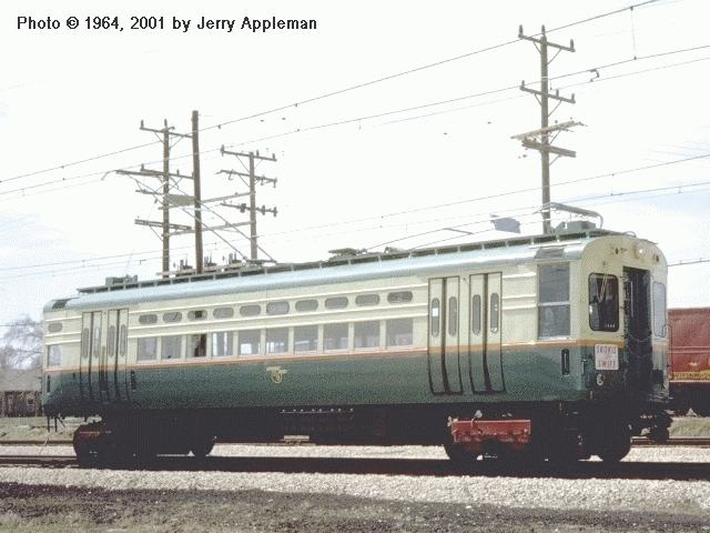
Experimental high-speed cars 1-4 were the first equipment rebuilt and assigned to the Skokie Swift.

Several years ago the Dunsel Line acquired an unused CTA 1-50 series car from the Chicago & Utopia Ry (Ed Halstead of Modeling Insull's Empire). This car will have its roof boards removed and replaced and will be equipped with CTA-designed trolley pans.

This car was previously owned by the late Dave of Dave's Rail Pix who equipped with car with CA&E trolley beams and sleet scrapers.

5000-series (as 51-54)

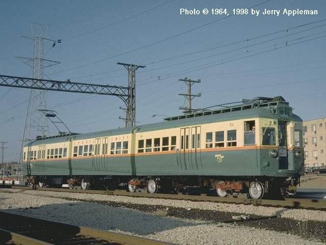
The second unit to be modeled is one of the most unique cars ever acquired by the rapid transit lines: the experimental 3-part articulated 5000-series cars. Like the 1-50, this car will also be equipped with trolley-pans. These four cars wandered the "L" system, not finding a permanent assignment due to some of the drawbacks of their design. They finally found a home on the Skokie Swift where their single unit, high capacity nature made them extremely useful. Once assigned, these cars remained in Skokie service for two decades before being retired.

61-65 series

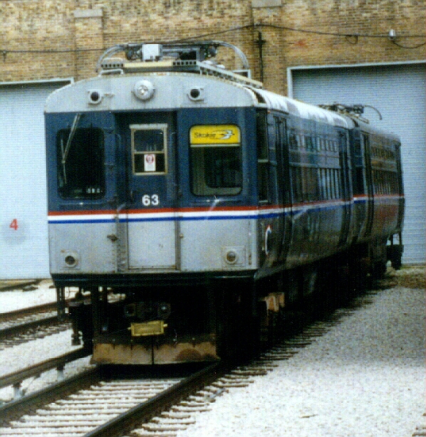
The next set represented the first instance of a pair of cars being assigned to the line. In reality, the 60s were little more than pairs of rebuilt 5-50s that had been semi-permanently coupled and equipped with single-arm pantographs. I have yet to acquire a two more 1-50s, but I'm always looking.

3200-series

The 3200-series represents the last set of Skokie Equipment. These cars came equipped with pantographs for operation on the Swift.

For this, I'll be extensively rebuilding a pair of MTH 3200-series cars. The only downside here is that while the cars operate on O gauge track, they aren't O scale. MTH did a pretty good (not great, but far from terrible) job with the detail put into the cars, but unfortunately they didn't scale them properly for 1:48. Instead of being 12 inches long, the cars are 12 3/4 inches long from anticlimber to anciclimber. This is, however, fortunate as the cars are then the proper length for 17/64 (Q) scale, or approximately 1:45. This means they're correct for the track gauge.

The scale difference between the 3200s (left) and the other two cars (both O scale) is evident.

In addition to the addition of roof boards and pantographs, these cars will have to be entirely rebuilt from the floor down and be outfitted with new interiors.

Lots to do!