Showing posts with label 3D modeling. Show all posts

Monday, October 19, 2015

Arches

I've been behind on updates since July and now I've got to try to catch up.

In addition to beginning work on the 5000, I also acquired new project. Back in October 2014, I purchased a set of Walthers North Shore ends on a whim. I had no plans for them and figured they might be useful down the road for trading or something. Later I was able to acquire a Walthers arched roof and mats. Again, purchased them only because they were available and decently inexpensive. (It should be obvious where this is going.) A few months ago I found a pair of Walthers “interurban sides” that were appropriate for a North Shore car. My new project is to assemble and complete this Walther’s North Shore kit. The car sides (specifically the window arrangement) put this car in the high 700s. I haven’t decided whether or not this car will be powered or even if it will be part of the Skokie Valley or Shore Line trains. It’s a low priority project; something for the backburner. In an email blast a while back, I saw a picture of a North Shore car built from a Walthers kit on the Salt Creek Lines. I’ve forgotten who built it, but it looked superb and betrayed nothing of its rather average beginnings. With the right amount of effort, I have high hopes that my planned car will look as good.

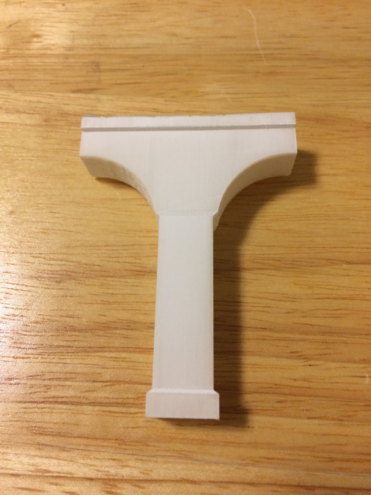
I've also done some 3D modeling. I went back and decided on a shape for the arches atop the support columns under the viaduct. I settled on useing a circle to create the curve of the arch although the shape of the actual arch is closer to a vertically squashed semicircle. The idea here is to make a mold of a 3D printed master since I’ll need fifteen middle columns and six end columns for the viaduct. I am yet to determine a method of actually doing this and I’ve also yet to select a material.

Circular arches. The green is simply a marker for how high the curb/sidewalks need to be and is not part of the model.

Once a suitable interior shape was developed to make the structure hollow (done to keep costs low[er]) I had it uploaded to Shapeways and printed. As soon as this went through, I suddenly realized a miraculously simple way of producing the "squashed semicircle" shape for the arches that I wanted. All that's required is drawing a circle and then rescaling it vertically, but not horizontally. The result is an oval.

"Squashed" arches. The difference is subtle, but the arches are a much closer match.

Meanwhile, the original design was printed and shipped out. The results were... less than optimal.

Looks okay so far.

Oh. That's not right.

Not sure where the surface stuff came from, but that should be easily sanded off.

It's difficult to see, but the piece is actually slightly curled.

I'm actually not too worried about it since the arches need to be redone anyway.

Friday, August 14, 2015

Pantographs and Trolley Beams

Strap in! It’s a long one.


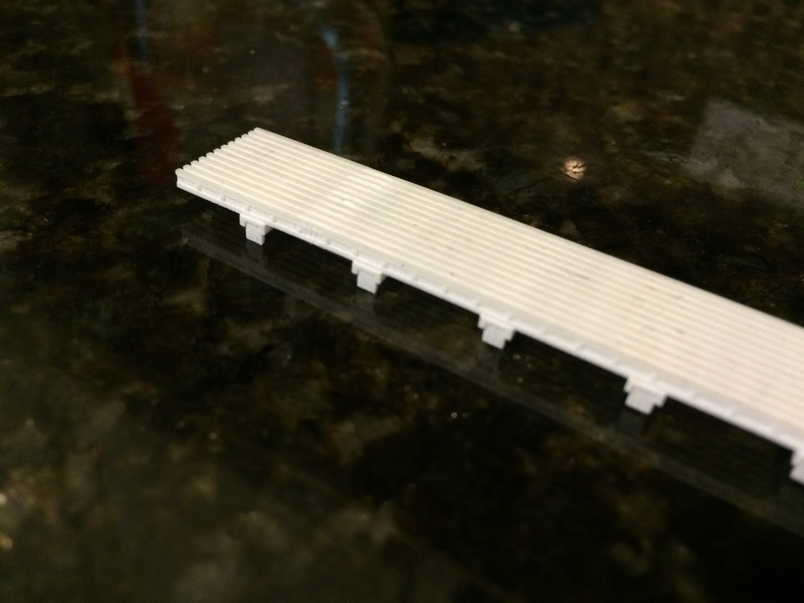
Since May I’ve made some headway on a number of projects. 3D modeling continues as always and on July 9, I received the first print of the experimental roof walks for the 3200 series cars. The walks in question are only the rear half, the portion that is only half-width. This was done as a cost saving measure for the test article.

The plan was to see how these came out and then work on and produce the front half which supported the pantograph. The two sections will line up and be glued together to form one complete piece. Instead of attempting to match the curve of the MTH roofs, I made the support brackets slightly longer than needed. Once glued together, I’ll place a piece of sandpaper on the roof and then gently rub the roof walks back and forth on top until they conform to the shape of the roof.

Unfortunately, after looking at the piece and being wholly satisfied with it, I began work on the forward portion only to discover that it would be visibly too wide for the car. To fix it, I needed to reduce the gaps between the horizontal members by 0.2mm each. Since the rear portion and the front portion have to line up, this meant that the rear portion needed to be narrowed as well, rendering the original one unusable.

I was able to make the rather tedious corrections relatively quickly and sent off for an updated version. Thankfully Shapeways was having a short term deal where shipping is free.

The narrowed rear portion of the roof walks arrived on the 16th and it definitely looks better than the original. The downside is that this was the first piece that I’ve gotten with some kind of a printing error. It arrived with a globule of “white stuff” which went across and between the slats in one section.

This didn’t come off while soaking in Bestine but did come off afterward after being cleaned with an old toothbrush under running water. Some of the slats were damaged (either in production or during cleaning—impossible to tell which) and from certain angles this shows. This end also has a strong odor of cherry syrup, which is highly unusual since 1) none of the other pieces have had this smell and 2) I can actually smell this with my barely functional nose! (The fact that I can smell it really attests to the strength of the smell.)

Otherwise, the piece came out well.

The damaged area is slightly visible from this angle. It is between the first and second supports on the left. In removing it, some of the top portion of the walk was damaged.

The original is at top. The newer one has been soaked in Bestine, giving a clear demonstration of what the agent does to Frosted Ultra Detail. Again, damage is visible here.

Tying in with the roof boards, my father and I took a trip out to the Illinois Railway Museum on Wednesday, July 8. While there, I was able to locate the pantographs from the 3200s and get some preliminary measurements. Now that I know where they are, I’ll be sure to acquire a very detailed set of measurements to be able to build the correct ones myself.

Progress has also been made on a new set of trolley beams for the same cars. I’m still working on perfecting the design of the third rail shoes themselves, but the equipment supporting the shoe has been designed and printed. This is a test to see how Frosted Ultra Detail handles separate-but-interlocking parts. (I would feel immensely satisfied if I could manage to produce dangling third rail shoes that could also glide on top of a rail.) If this fails, I can at least manufacture a set of trolley beams for the 3200s that don’t have provision for sleet scrapers on the rear trucks, as is prototypical.

The test piece also arrived on the same day as the narrowed roof walks. The two loops which hang down and connect to the third rail shoe do dangle, but not as freely as I’d hoped. Soaking them in a bath of Bestine did help, as did working them a bit, but they still don’t swing completely freely. I’m hoping there’s some kind of lubricant I can try to make them work better. I’d rather not resize the parts to improve “functionality” as areas on this piece are already pushing the limits of Frosted Ultra Detail in terms of minimum width and also because this would alter the look of the piece.

Perhaps it’ll work better once the shoe itself is added. Fingers crossed.

I actually printed this piece in Frosted Extreme Detail (which is the same material as FUD, but printed with thinner layers). The difference in cost for such a small piece ended up being 10¢ and I figured a dime was worth the expense of finding out what the big deal was.

Ultimately I don’t see too much of a difference and it certainly doesn’t seem to be worth the extra cost for larger pieces.


Additionally, I purchased a pair of Japanese pantographs from the East Gary Car Company. These pans are supposed to be junk, but as it’s the shoes I’m interested in, that doesn’t matter. I am fortunate enough to know someone who has a small, but overfilled workshop. He had a spare rotary tool (Ryobi, not Dremmel) that he didn’t want taking up space and he gave it to me. (One tool down that I don’t have to purchase!) Using this, I have already cut apart the shoes on one of the pans. (So far no complaints about the Ryobi.) These shoes (of which there will be four in total) will be for the 1-50 and 5000 series trolley pans. I still need to gather more information on the trolley pans before continuing much further down this road.

One of the big things holding me back on the 1-50 (car 2) and the 5000 (car 52) is my lack of a soldering iron. I’ll need this not only for the construction of the trolley pans, but also to remove the existing roof boards on both cars. I’m already stretching money a bit so this isn’t something I’ll be purchasing in the immediate future.

A tase of things to come

Still, progress continues. The middle section of car 52 doesn’t (and never did) have roof boards since there never was any trolley equipment located there. This makes the middle section an ideal place to start. I’ll prime this section as soon as possible.

The wheels on the 52 are another issue. As built, the 5000 series cars were equipped with resilient wheels. By the time the cars were assigned to the Skokie Swift and rebuilt, these wheels had been replaced with standard equipment.

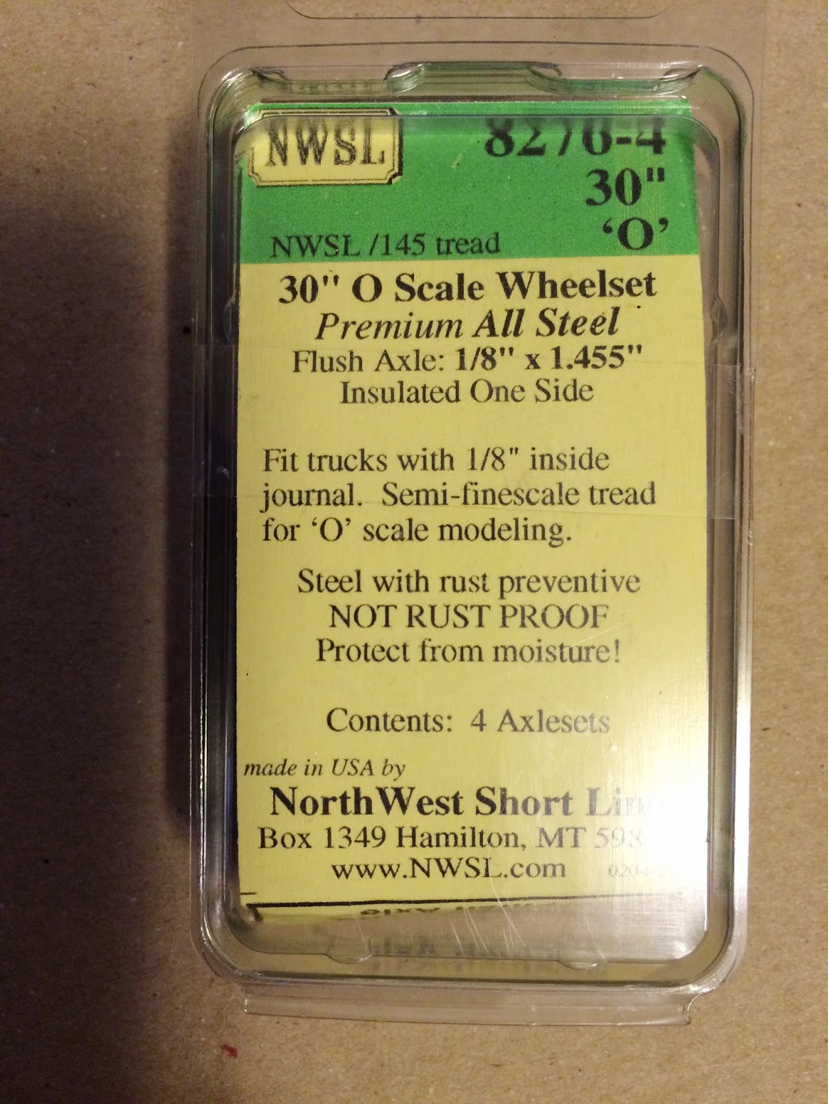
The trucks supplied with the car are correct in appearance (they’re actually a fair sight better than the CTA 6000/1-50 Clark B3 trucks from Q Car) so I’ll be keeping these and replacing the resilient wheels currently on the model with “regular” 26” flush wheels from NorthWest Short Line. I haven’t decided on what to do with the power trucks yet. (I’m not even sure that the wheels are insulated. I have a strong doubt that they are.)

Wednesday, June 24, 2015

Overdue update

After a long wait the, trucks for one of the Skokie Valley cars came in. (Both cars had the same trucks.) While I’m happy to have finally gotten these, they did not arrive without a small bit of frustration. The order was for a power truck with two Magic Carpets and a trailer truck. What I received was a pair of power trucks, each with one axle powered. I could alter the trucks to my original specifications, but I’ll probably just leave them as they are and go from there.

These are NorthWest Short Line Magic Carpet IIIs installed in Q Car Baldwin 8430AA sideframes. I opted not to get the sideframes with North Shore trolley beams so that I could devise and 3D print my own insane trolley beams with free hanging third rail shoes. If this fails, I'll acquire the appropriate Q Car trolley beams and attach them myself.

I took the opportunity of having a day off for Memorial Day to head out to the Illinois Railway Museum. They had (I believe) five trains in operation: a pair of CA&E woods, a pair of 4000 series “L” cars, the Zephyr, a steam train, and the CTA’s 2200 series cars. The 2200s were on town shuttle duty, operating on a short trip from 50th Avenue to Jefferson Street (the western end of the line) and back.

While I did take the opportunity to ride some trains, I was primarily there to complete and expand the measurements I took back in October.

In addition to more CA&E and North Shore equipment, one of the things I really want in O scale is a pair of 2400 series cars. Unfortunately, their numerous compound curves are fairly daunting and I haven’t yet conceived of a method to reproduce them properly.

Instead of attempting to tackle this task outright, I decided to try something “similar,” but with a much simpler design. The 2200 series, with its rectilinear forms and multitude of sharp angles was the clear and obvious choice. Drawings for the 2200 series were already available in CERA bulletin 115, Chicago’s Rapid Transit Volume II: Rolling Stock/1947-1976. I started with these drawings and then moved to taking field measurements at IRM. The plan was to do this at the end of the season in October and work on them over the winter, but the museum threw a monkey wrench into the works by moving the 22s away from the 50th Avenue station with its high-level platform. Here was the chance to rectify the situation.

I arrived on site around 9:30 and wasted no time in getting to business.

For the moment, the aim isn’t to produce a whole car. (That is, of course, the eventual goal.) I want to see how well I can produce a car side and then improve the design or (if satisfactory) continue the car to completion. To this end, my efforts were on filling in the missing measurements on the car sides and things couldn’t have gone more smoothly.

I have no idea what led me to believe that this would be a relatively simple “warm up” project. There are so many “minor” details which (if ignored) would end up drastically changing the shape—and therefore the look—of the model. Even without complete measurements, the car is definitely beginning to take shape.

Due to the costs involved, I’ll print a test “strip” to determine how well things are coming out and if there is anything that needs to be fixed. (Shapeways gave me a warning about the grill for the vent at the bottom of the car and I want to see how well this comes out before shelling out for the whole side.)

Ultimately the kit will be made of 5 parts per car, with the sides of the cars being produced as one long piece. Fortunately the car sides are just short enough in 1:48 that they barely meet the length limitation for Frosted Ultra Detail. As of right now, each side will cost just under $100 to make, but this doesn’t factor in the reduction in wall thickness at the doors or several other details that (when finished) will reduce the total material used.

I also got a few measurements for the Form 5 coupler. (I’d been having some difficulty with one particular area which I couldn’t get to look right.) With any luck I should be able to have a pair of 1:45.2 scale couplers for the 3200s rather soon. Once successful, O scale couplers will follow.

Thursday, May 7, 2015

April on the Dunsel Line

As predicted, April was a slow one on the Dunsel Line. There were no new purchases even though some were available. A pair of CA&E 450s was out there, but I passed these up. It’s just as well. I’ve already got two North Shore trains to work on in addition to the Skokie Swift pieces. Makes sense to at least try to finish some of this stuff, right?

As planned, I went ahead with more 3D modeling projects for the 3200 series cars. Unfortunately the Form 5 coupler is still not complete. My own attention to detail is really getting the better of me here. At this point I’m primarily stuck on one specific section of this model and lately I haven’t wanted to think about it so I’ve been avoiding it. (Not exactly an attitude that’s conducive for getting things done.)

Another project which I have been modeling is the steps for the 3200s. For whatever reason, when MTH made these cars, they didn’t include the steps. I suppose this stemmed from the same issue with getting the underbody equipment totally wrong. (Thankfully, when they produced the 6200 series, they fixed both of those issues.)

This is actually been a project that I’ve been working on since my last trip to IRM. For such a simple model I’ve really spent far too much time reworking things to get them right. Early on I kept getting holes in the model that refused to be patched and I hadn’t yet discovered the “intersect with selection” method which is necessary for making the angled portions of the side steps.

This method involves drawing a shape (in this case it was a rectangle) shifted to the appropriate angle and then moved to intersect the part of the model that needed to be “cut” at an angle. Once in place, both parts (the shape and the model) were selected and right clicked. This brings up a menu from which intersect is an option. It has two suboptions: “intersect with model” and “intersect with selection.” Intersection basically finds all the points of intersection between the two pieces and draws definitive lines at these points and incorporates them. From here the rest is easy; all that’s left is deleting all the unnecessary parts.

I wasn’t satisfied with how they looked on my computer in Sketchup or in the Shapeways render. They looked too thick to be right. I had to remind myself that the sides came out to be 0.6mm thick, the smallest workable size in Frosted Ultra Detail and this was thin enough to look good on the snowplows. Despite my misgivings I had them printed anyway and they arrived today. I am extremely pleased with how they turned out. This should serve as a reminder that I really should just take a deep breath and relax. (But it won’t.)

Speaking of the snowplows, I have made a discovery: they’re too wide! How frustrating. The angled bars at the top along side of the framing are supposed to fit neatly within the gap under the anticlimber. Unfortunately, the model plows are about 1mm too wide to fit within this space.

Attempting to rescale the snowplows didn’t work either. (Unlike the steps, the snowplows weren’t drawn full size and then scaled down. I mathematically scaled down the dimensions and then rounded these numbers to fit within the Frosted Ultra Detail guidelines.) In order to get them right I’ll have to redraw them. (All dimensions save for the width are correct, so cutting out 1mm from the center won’t work as this will decrease the distance the snowplows protrude from the ends of the frames.)

I’m not looking forward to this, but I’ll make the necessary modifications because it will gnaw on me until it’s right.

Another project I’ve been working on is the full-width cab partition in its closed state. (I’ll also be making one in the open state; that is, one where only the motorman’s position is closed off to the public.) This is nearly ready and is publicly visible in my list of designs on Shapeways. I’m still not satisfied with a few details at the moment. Something looks off about the position of the windows in relation to the “bar” above the cab door. I’m going to take some more measurements before finally sending this one out to be printed.

In addition to checking and/or correcting the window heights, the door handle also has to be finished.

The wheels which I ordered from Northwest Short Line arrived and—as expected—look good. Now I just need to build a pair of trailer trucks for them. But since these have arrived, I found myself wondering about the trucks I ordered for the Skokie Valley train. I placed the order for these in early to mid January and still haven’t received them. Apparently they’re still waiting on parts, but at least the order wasn’t lost!

These aren't 100% correct, but the difference between 30" in 1:48 and 28" in 1:45.2 is so close that getting the commercially available set is close enough.

A side view of the wheels.

Tuesday, March 31, 2015

March in Review

Let’s get straight to the point; I spent a lot of money this month. Even though I’d planned on spending a good deal of money on models this month, my actual total greatly exceeds my anticipation (and this doesn’t even cover routine things like food and bills). I had a number of other projects (not model related) that also cost more than expected, so April will almost certainly be a very quiet month around here.

With that said, it seems like a good time to stop and reflect on a very expensive (but good) month. March is the month of the Chicago O Scale Meet (also known as the March Meet) and associated open houses at various trolley layouts. Preparation for these two prompted me to get back in gear and begin working on the 3D model of CTA’s form 5 coupler.

Ultimately this design wasn’t finalized in time for the open houses (I was only able to attend one) and the design work is still ongoing. The continuation of this project should be a nice one to carry on into April.

Before the meet I was able to get my hands on a Clouser North Shore steel coach. Although it did not come with trucks, I did get a good deal on it and am very happy with my purchase. The following week was the March Meet and there I bought a brass North Shore 170-182 series coach. Acquisition of this car has enabled me to outline and define my projects for the North Shore Line. I’d already decided on modeling the North Shore circa 1952/1953 (the same years for the CA&E) and the addition of these two older steel cars has led me to separate my efforts into the creation of two trains: Chicago-Milwaukee via Skokie Valley (the combine and upper 700) and a Chicago-Waukegan Shore Line train (the “older” coaches).

I have already ordered a motor truck set that would be applicable to either car on the Skokie Valley train, so I’m waiting for that to arrive. I’ll have to construct a test track pretty soon, which I suppose will be the very beginnings of my layout.

Also at the O Scale Meet I bought a pair of pantographs to turn into sausage. The shoes on these will be cut apart, to produce four “single” pantograph shoes. Each of these will be mounted at the end of a pair of four-spring horizontal trolley poles. I still need to buy a total of eight trolley poles for car 2 (the 1-50) and car 52 (the 5000) to make this. As a result of... overspending... I probably won’t begin this phase of that project in April.

After the March Meet I went back and made complete 3D models of the 3200-series snowplows. After increasing the size of the nuts so that they would register at Shapeways, these were sent off to the printer. They arrived on Monday and I am extremely pleased with the results. I’ve already made these available via the Ravenston Car Company at Shapeways. (Shameless self promotion!)

In continuing work on the 3200s, I ordered a set of wheels from NorthWest Short Line. I had planned on mounting these inside of cheap, temporary trucks (shop trucks) but I’ve abandoned this idea in favor of 3D printing my own set of “test trucks” which will enable me to try a few things out and see how well this will actually work. Unfortunately, 30” wheels are on backorder for about a month, so this particular project will probably have to wait for a while. In the meantime I’ll see if I can gather some pictures of the Duewag trucks with which the cars are equipped.

I know someone who claims (strong emphasis on “claims”) that he has access to equipment to make metal casts and, if all goes well, I should be able to make molds of the 3D prints and produce a series of metal trucks.

Even after the end of the March Meet March continued to be a money spender! I found another brass 1-50 series car and didn’t hesitate to grab it. To model the four basic iterations of Skokie Swift equipment as planned, I need a total of three of these cars: one as for a single-unit 1-50 and two for a double-unit 60. I now have two.

My first 1-50 has a dent on one end which I should be able to hammer and fill back into shape. Regardless of how well this turns out, the original (dented) 1-50 will now be used as part of the 60 pair with the dented face being positioned between the cars to minimize its visibility. The new car will now be the single and will get the CTA designed trolley-pans.

I also started work on a 3D model of the resistor grids for the 3200 series. This model uses measurements taken from the pair of 2400-series cars at the Illinois Railway Museum. There are subtle differences between the 2400 and 3200-series equipment that I have to account for and I’m currently working with the design to get it right.

The benefit of creating this model in full scale and then reducing it is that it can effectively be used to create specific models for the 2400, 2600, and 3200-series cars with only minor variations in each and scaled appropriately to 1:45 for the 3200s and to 1:48 for my planned 2400s and 2600s.

The 2200-series cars (which I have already started designing) used a resistor set that was substantially different than those used on the later cars. During my last trip out to IRM, I didn’t take underbody measurements for the 2200s, so I won’t be able to continue work on that particular set until I make another trip out to Union.

Finally (my wallet has its fingers crossed that this really is finally) I found a power truck set that would be appropriate for either car in the Skokie Valley train. It matches the truck I ordered from NorthWest Short Line, although at present I don’t know if the motors are Magic Carpet IIs or IIIs. The main impetus for getting this truck was the fact that I was able to get it for a substantially lower price than normal.

Moving forward into April my projects are most likely going to be all 3D modeling as this can be done at no cost. I plan to finish the form 5 coupler, work out the kinks with the resistors, and begin creation of an underbody set for a 2400-series pair (since I have photos and measurements on hand for that). I’ll also be continuing to fabricate the replacement car floor for the second 3200-series car.

Friday, March 20, 2015

Back to Business: Snowplows Again

The Dunsel Line shops are predominantly (literally) a virtual operation at this point. Naturally, most work done there is done on the computer.

I’ve decided to take a brief break from designing the Form 5 coupler and go back to an earlier project: the Q scale (1:45) snowplows for the 3200s. Previously I had stated that I would produce the snowplow “blades” from cardstock and glue them to the 3D printed frames I’d produced. I’ve decided to scratch that idea and just have the whole thing printed as a complete piece. This opens up the product for anyone else who would desire to reequip their MTH 3200s and/or 2-rail them.

On Sunday I went back in and added the blades and accompanying parts.

I think they look pretty good. And, better yet, they pass the tests for Frosted Ultra Detail. They’re ready to print!

Not so fast. Wait a minute… Where are the nuts holding the blade to the frame? They’re in my 3D model and they’re of a size that’s printable in FUD.

This is Shapeways' preview image. As you can see, the nuts pictured in the 3D model are not present here.

This is really starting to piss me off. This is the third time parts have gone missing when I've uploaded a model to Shapeways. (I am not blaming Shapeways for this error.) Somewhere in the conversion from the .skp file to .dae (done in Windows via "File" > "Export" > "3D model...") parts go missing and I still can't figure out why.

I'll delay printing until I solve this constant issue.

But in other, non-virtual, news I've begun fabrication of the car floors for the 3200s. I'm using 0.060" Evergreen styrene.

The holes drilled in the floor mark where the trucks will be mounted. If you have a sharp eye you've noticed that one of the holes doesn't line up with the line drawn down the length of the car body. This is not an error. The hole is correct, the line is off on that end by about 1/16". Since I won't be reusing the trucks the cars came with, I'll have to build my own and I'll be purchasing a set of wheels from NorthWest Short Line soon.

The 3200s are equipped with 28 inch wheels. In 1:45 scale, this comes out to a diameter of 0.622 real inches. 30 inches in O scale comes out to 0.625 real inches. The 30 inch wheels will therefore be 0.003 inches too wide, but I'm willing to settle. Once I get the wheels, I'll acquire a pair of cheap trucks for the floors to sit on while work progresses.

Thursday, March 5, 2015

CTA's Form 5

I haven’t fallen off the face of the Earth! (Not yet. Give me time.) There are still a number of issues that continue to plague me with the seats for the 3200 series and I haven’t yet decided on the course of action to take in that direction.

Instead I’ve refocused my efforts into another part of this project which will affect additional projects that I have planned. In CERA Bulletin 115 are plans for the Form 5 coupler. This coupler (with slight modifications) has been used on every series of “L” car from the original 5000 series onward.

Once the grounds at the Illinois Railway Museum open, I’ll make a trip out there to continue gathering measurements for the 2200 series cars. Once I have the appropriate numbers, I’ll finish the 3D model I’ve created and produce a 2200 in true O scale. (Island Model Works produced a rehabbed 2200 series shell that was designed to fit onto the MTH 3200 series chassis. The MTH cars are oversized and are closer to 1:45 scale than 1:48.)

Since the Form 5 is used on both the 3200 series and on the 2200 series, this seemed like a logical place to go.

The MU connections haven’t been added yet, and as you can see, there are other details that haven’t yet been modeled. My goal is to have this printed and in my hands in time for the O Scale Meet (March 14) although I’m beginning to suspect that this might not happen.

The 3D model pictured above represents a departure from my previous models in that it is designed in full scale. This has the advantage of being easier to work with (Sketchup doesn’t like small numbers) and easier to rescale at will. The initial print will be in 1:45 scale so it will be suitable for the MTH 3200s and the Island Model Works 2200s. Once I’m satisfied with that, the plan is to produce a set in 1:48.

Friday, December 26, 2014

Erroneous Values!

So, after pulling my hair out trying to find this separate piece, I gave up and decided to reduce the thickness of the "finished floor" by 1mm just to see how much money this would knock off the total price. It turns out 1mm translates out to about an $18 savings. More importantly, though, the product no longer registered as having "thin walls" or multiple parts! The loose piece didn't exist (thank goodness) and, as designed, all of the walls were reading as having acceptable dimensions. The problem was just some mathematical artifact in the file's coding picked up from somewhere. The new, thinner, file didn't have such errors. Success!

But wait. Not so fast. I knocked off a few more millimeters here and there (things I decided weren't essential and probably wouldn't actually help much) just to see how much more I could get the price to drop, uploaded the new file to Shapeways, and suddenly two of my old friends reappeared. Now knowing what to look for, I was able to find them much more quickly. For some reason, part of one of the seats was not registering and this was causing the stanchion connected to that seat to be attached to nothing. (This is where the multiple parts issue came from.) The other problem, it turns out, is being caused by a shape emanating from one of the windbreaks. This shape is too thin for the printing constraints.

Here's the kicker: none of these issues are representative of the 3D model I've created. I can't just fix them on my end, because they're non-existent. This means that there's either an error in the exporting process from Google Sketchup's native file format (.skp) to Collada (.dae) which is one of the acceptable file types for Shapeways, or the problem is with Shapeways and they way their computers are reading such files.

Either way, I have no solution at present.

Wednesday, December 24, 2014

Virtually Completed

No pun intended.

Work on the interior of the 3200s has progressed and I have, at last, acquired all the necessary measurements to build the center section of the car to my satisfaction. Once again, to assure proper alignment in the car (and to make sure they don't fall over in the process) I've designed the seats to be affixed to a thin "finished floor" which will be mounted on top of the real car floor. The car is then divided into three sections: front, middle, and rear. My efforts have been focused on the middle section and it's almost ready to be sent off to the printer.

Shapeways digital preview of the middle section

This seating configuration is for an odd numbered car. The even numbered cars have a box next to the single seat by the windbreak.

The view down the aisle toward the front of the car.

There are holes or reductions through the floor and behind the door pockets. These serve not only to reduce the material needed (and thus the cost) but also to allow multiple points to hide wires to and from the roof.

The thickness of the floor here is not final. It will be reduced sometime in the (hopefully near) future once I determine what material I'll be using for the car floor and how thick that material is. I also have to figure out how wide the floor grooves are in the aisle of the car so that the proportions will look right. Some will say, "But you won't see the floor grooves in the model!" My response to that is simply that I don't care. (It will satisfy my brain to know that they're present.)

Lest things turn out to be too easy, there, of course, have to be some problems. In this case there are three. The first problem is that while all of the components individually check out for printing, the combined object somehow fails the wall thickness checks. (Don't ask me to figure out how that makes sense. As far as I am aware, my 3D models are not on any kind of exercise/diet regimen.) This is easily overcome by the "print it anyway" option.

The second problem is that whenever I upload or modify the file, it keeps registering as being a two part object by Shapeways. At first it registered as a four part object, then I discovered that two of the seats were actually hovering about 1/20 of a millimeter above the finished floor. I have looked and looked, but for the life of me, I cannot find the remaining "separate" piece and I'd really rather not print this thing off, only to have it come back with something integral rattling around in the box.

The third, and most predictable, problem is cost. As of right now I'm looking at about $108 to have this thing printed. (And this is only the middle section. For one car.) Yes, the price will drop once I reduce the thickness of the floor, but not by that much. This price pretty much killed what little hope I had for selling these to other people interested in making their 3200s look better.

A cage will eventually be added to protect the poles from snapping off in shipping.

Friday, December 12, 2014

Initial System of Subways entrance

This is one of those other projects I mentioned. This is a full scale model of an original entrance to an Initial System of Subways (State and Milwaukee-Dearborn subways) station, excluding North/Clybourn. Obviously, this model has not yet been finished.

I got the idea after seeing a number of subway entrances available in multiple scales for the New York City Subway, but being immediately aware of any subway entrances for Chicago. The other motivation is CTA's "Your New Blue" program which promises, as part of station renovations, to obliterate the last remaining original style entrances. Creating 3D models (and scale models) is my small bit for historical preservation.