Showing posts with label trolley beams. Show all posts

Friday, August 14, 2015

Pantographs and Trolley Beams

Strap in! It’s a long one.


Since May I’ve made some headway on a number of projects. 3D modeling continues as always and on July 9, I received the first print of the experimental roof walks for the 3200 series cars. The walks in question are only the rear half, the portion that is only half-width. This was done as a cost saving measure for the test article.

The plan was to see how these came out and then work on and produce the front half which supported the pantograph. The two sections will line up and be glued together to form one complete piece. Instead of attempting to match the curve of the MTH roofs, I made the support brackets slightly longer than needed. Once glued together, I’ll place a piece of sandpaper on the roof and then gently rub the roof walks back and forth on top until they conform to the shape of the roof.

Unfortunately, after looking at the piece and being wholly satisfied with it, I began work on the forward portion only to discover that it would be visibly too wide for the car. To fix it, I needed to reduce the gaps between the horizontal members by 0.2mm each. Since the rear portion and the front portion have to line up, this meant that the rear portion needed to be narrowed as well, rendering the original one unusable.

I was able to make the rather tedious corrections relatively quickly and sent off for an updated version. Thankfully Shapeways was having a short term deal where shipping is free.

The narrowed rear portion of the roof walks arrived on the 16th and it definitely looks better than the original. The downside is that this was the first piece that I’ve gotten with some kind of a printing error. It arrived with a globule of “white stuff” which went across and between the slats in one section.

This didn’t come off while soaking in Bestine but did come off afterward after being cleaned with an old toothbrush under running water. Some of the slats were damaged (either in production or during cleaning—impossible to tell which) and from certain angles this shows. This end also has a strong odor of cherry syrup, which is highly unusual since 1) none of the other pieces have had this smell and 2) I can actually smell this with my barely functional nose! (The fact that I can smell it really attests to the strength of the smell.)

Otherwise, the piece came out well.
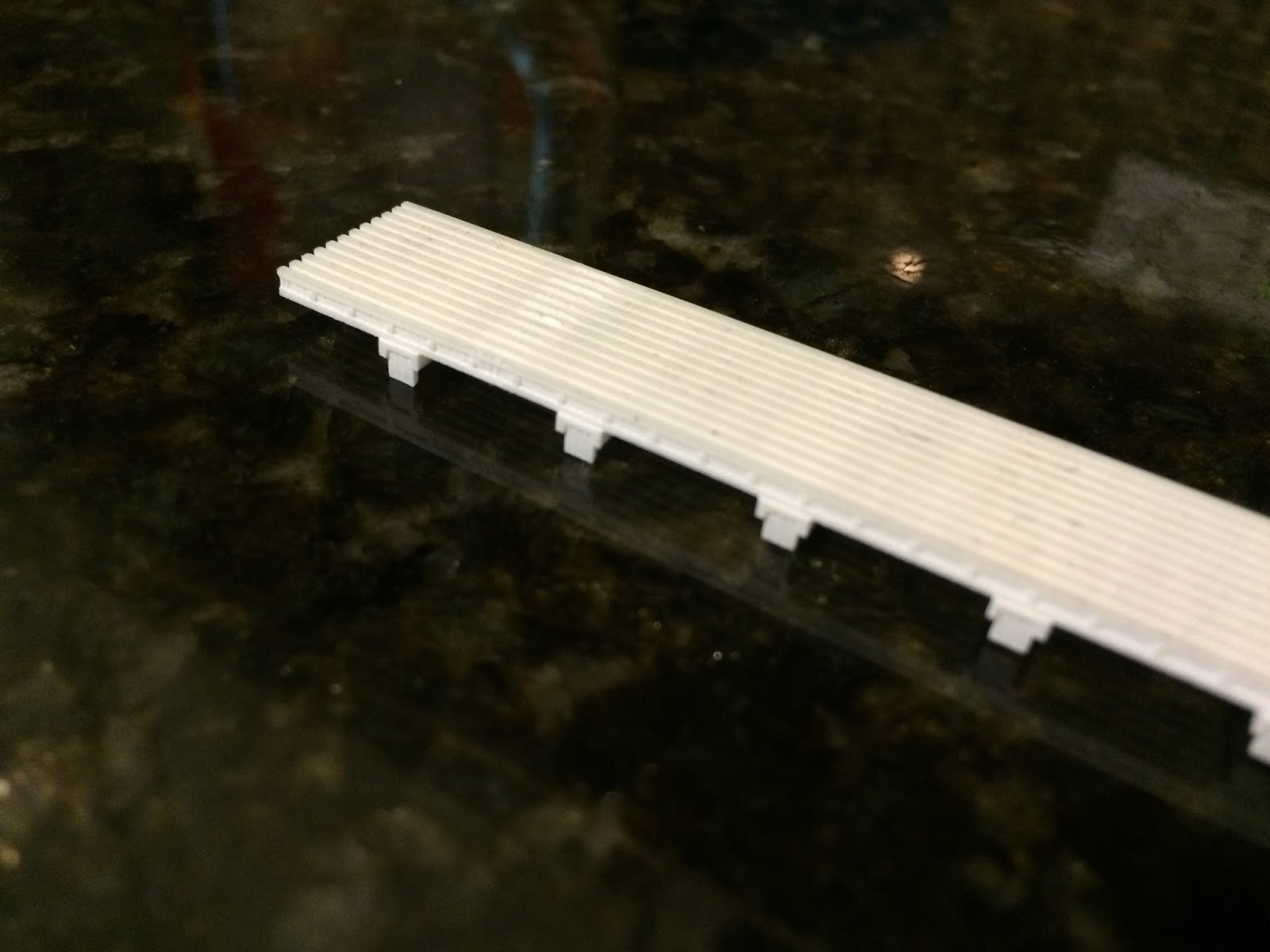
The damaged area is slightly visible from this angle. It is between the first and second supports on the left. In removing it, some of the top portion of the walk was damaged.

The original is at top. The newer one has been soaked in Bestine, giving a clear demonstration of what the agent does to Frosted Ultra Detail. Again, damage is visible here.

Tying in with the roof boards, my father and I took a trip out to the Illinois Railway Museum on Wednesday, July 8. While there, I was able to locate the pantographs from the 3200s and get some preliminary measurements. Now that I know where they are, I’ll be sure to acquire a very detailed set of measurements to be able to build the correct ones myself.

Progress has also been made on a new set of trolley beams for the same cars. I’m still working on perfecting the design of the third rail shoes themselves, but the equipment supporting the shoe has been designed and printed. This is a test to see how Frosted Ultra Detail handles separate-but-interlocking parts. (I would feel immensely satisfied if I could manage to produce dangling third rail shoes that could also glide on top of a rail.) If this fails, I can at least manufacture a set of trolley beams for the 3200s that don’t have provision for sleet scrapers on the rear trucks, as is prototypical.

The test piece also arrived on the same day as the narrowed roof walks. The two loops which hang down and connect to the third rail shoe do dangle, but not as freely as I’d hoped. Soaking them in a bath of Bestine did help, as did working them a bit, but they still don’t swing completely freely. I’m hoping there’s some kind of lubricant I can try to make them work better. I’d rather not resize the parts to improve “functionality” as areas on this piece are already pushing the limits of Frosted Ultra Detail in terms of minimum width and also because this would alter the look of the piece.

Perhaps it’ll work better once the shoe itself is added. Fingers crossed.

I actually printed this piece in Frosted Extreme Detail (which is the same material as FUD, but printed with thinner layers). The difference in cost for such a small piece ended up being 10¢ and I figured a dime was worth the expense of finding out what the big deal was.

Ultimately I don’t see too much of a difference and it certainly doesn’t seem to be worth the extra cost for larger pieces.


Additionally, I purchased a pair of Japanese pantographs from the East Gary Car Company. These pans are supposed to be junk, but as it’s the shoes I’m interested in, that doesn’t matter. I am fortunate enough to know someone who has a small, but overfilled workshop. He had a spare rotary tool (Ryobi, not Dremmel) that he didn’t want taking up space and he gave it to me. (One tool down that I don’t have to purchase!) Using this, I have already cut apart the shoes on one of the pans. (So far no complaints about the Ryobi.) These shoes (of which there will be four in total) will be for the 1-50 and 5000 series trolley pans. I still need to gather more information on the trolley pans before continuing much further down this road.

One of the big things holding me back on the 1-50 (car 2) and the 5000 (car 52) is my lack of a soldering iron. I’ll need this not only for the construction of the trolley pans, but also to remove the existing roof boards on both cars. I’m already stretching money a bit so this isn’t something I’ll be purchasing in the immediate future.

A tase of things to come

Still, progress continues. The middle section of car 52 doesn’t (and never did) have roof boards since there never was any trolley equipment located there. This makes the middle section an ideal place to start. I’ll prime this section as soon as possible.

The wheels on the 52 are another issue. As built, the 5000 series cars were equipped with resilient wheels. By the time the cars were assigned to the Skokie Swift and rebuilt, these wheels had been replaced with standard equipment.

The trucks supplied with the car are correct in appearance (they’re actually a fair sight better than the CTA 6000/1-50 Clark B3 trucks from Q Car) so I’ll be keeping these and replacing the resilient wheels currently on the model with “regular” 26” flush wheels from NorthWest Short Line. I haven’t decided on what to do with the power trucks yet. (I’m not even sure that the wheels are insulated. I have a strong doubt that they are.)

Sunday, September 21, 2014

Success on Two Fronts

Okay, so this update is long overdue. In the intervening weeks I have had some successes with my models and my "layout." I have come to the decision (largely in part because of the purchase of the 2000-series cars) that the Dunsel Line will not be a traditional trolley layout. It will be a two-rail layout equipped with dummy third rail. This will allow operation of CA&E, North Shore, and "L" equipment even if the cars (such as the 2000s) are not equipped with trolley poles or pantographs. This will necessitate the pole- or pan-equipped cars to built to accommodate two modes of running, as they should be. This does come with a downside.

Prototypical placement of the third rail on the "L" has the top of the third rail 6½ inches above the top of the running rail and 20-1/8 inches from the inside edge of the running rail to the center line of the third rail. Contact with the third rail is made by a metal shoe (or a paddle in the case of very early AE&C cars). Contact with the third rail is made by gravity: the shoe naturally hangs and then glides across the surface of the rail when present. The problem here is that most on models, the shoe has been made in the free hanging or "down" position. This is fine for trolley operation as when under wire, the shoes should hang freely. With prototypical third rail placement, the shoe now hangs too low for operation. The MTH "L" cars have the shoe in the up or "on rail" position. This works well for prototypical placement unless the third rail is on the non visible side of the model or at gaps. In these situations the shoe isn't hanging when it should be.

A trolley beam on a St. Petersburg 2000-series car. The shoe is depicted as hanging free. This would collide with a prototypically placed third rail.

MTH made the shoe in the "on rail" position.

There are three ways to work this problem. The first is to use the commercially available trolley beams in the free hanging position and adapt the height of the third rail accordingly. The other is to use the on rail position and place the third rail according to where it will be seen by the viewer. I'm not entirely satisfied by either of these options.

The third option is, if at all possible, is to create a trolley beam with a third rail shoe that functions like the prototype so that it can glide or dangle as need be. I'm a neurotic freak so this sounds extremely satisfying. I had this idea in the past, but dismissed it due to my inability to construct such a small thing effectively. But now I can have things 3D printed! And according to the specifications on Shapeways' site, many materials do allow for moving parts if proper clearance is built into the design. Looks like I've got a new project...

Granted, this won't take into account the placement in the third rail given the difference in scales (1/48 vs. the 1/45 for the MTH cars) but I'll just have to live with it.

This actually leads to the first of my successes. The prototype seat for the 3200-series cars arrived from Shapeways on Monday and I’m pleased with the results.

This took far longer than I’d expected and was also fraught with no small amount of frustration. The first problem was getting the angle of the seat back to my own satisfaction (picture a weirdo riding the Ravenswood messing around with perfectly normal seats with a protractor and a crude, improvised plumb bob). The next (and far more frustrating) bit was to create the handhold on the back of the seat.

I was very much relieved to discover that the handholds on the 3200s are much simpler than their counterparts on the 22-, 24-, and 2600-series cars. Until I tried to produce them, that is. The process involves making an appropriately sized circle which will be the “pipe” in question and then drawing a curved line representing the path of the pipe. In this case, the path went up from the circle, curved to one side, continued horizontally, and then curved down to the same height at which it started. Once that path is created and placed on the appropriate plane (another interesting quest in of itself) and positioned with the start at the center of the circle, the “follow me tool” is used to extrude the circle along the specified path. Simple. Or not, as I kept getting error messages that people in Youtube videos never seemed to get.

Once I realized that the problem was that some combination of Google Sketchup and my computer was being a lazy pile of rancid horse turds, the project moved along swiftly. (No Skokie pun intended.) My problem was that I was trying to create the curve in 1/45 scale. This was simply too small for the program to handle. It wouldn’t do the math. However, once I scaled up the curve/circle combination to a large enough size, I was blessed with numerous beautiful curved pipe segments. Armed with this, I used the scale tool to reduce the piece to the appropriate size, and voila! (Apparently Sketchup has no problem rendering such a small thing, it just doesn’t want to draw it.)

Once that hurdle was cleared, I saved my file, exported it as a .dae (which is a file type native to Sketchup 8 and can be read by Shapeways) and sent the .dae off to be printed. And like that, it was done.

The question I keep getting asked when I’ve shown this thing around is, why did you only make one? I wanted to produce one seat just to determine what the end product would look like on a simple design and then rework my design from there. A single transverse seat seemed like the best option. This was printed in “Frosted Ultra Detail.” There are other (cheaper) alternatives available, however none of the other materials were sufficient to produce the detail included and wouldn’t pass some of the initial checks.

There was a slight (and I do mean slight) problem in the printing process. I didn’t include the stanchion that connects to the handhold on the back of the seat, but I did include the connection for it. This is the little nodule in the corner. This is an object that is shaped almost like an inverted, blunted, ogive cone. It is quite diminutive, but still bigger in diameter than the bar itself. The problem is that it didn’t print fully. There’s a “gap” in the back. Fortunately, it is so tiny that it isn’t very noticeable.

Now that I’ve seen what it looks like, I can say I like it and I can go ahead and make up the other variants. (Assuming I don’t go back and try to add the curves to the seat back and “cushion.”)

This still leaves the problem of the stanchions themselves. Still haven’t figured that one out just yet.

The second success is that the Dunsel Line has acquired a new piece of rolling stock! I am still waiting for it to arrive, but it is a high numbered 700 North Shore Line car in brass. (My knowledge of the North Shore isn’t what it should be, so I can’t identify the specific series until I consult my father’s CERA bulletins.)

This is my first North Shore model. The model didn’t come with trucks, trolley poles, or even a box. (This is why I it wasn’t identified when I purchased it.) What it does have is a few dents on the roof and some tarnish in a few spots, but these things should be easily fixed.

The plan here is to paint it in the final variant of the North Shore’s green and red and equip it with appropriate Q Car Company trucks insulated for two rail operation. Power will be supplied by a pair of NWSL Magic Carpets. A selector switch will, of course, have to be installed for two rail or trolley power. Poles will also be Q Car.

Exciting times ahead!