Friday, December 12, 2014

Initial System of Subways entrance

This is one of those other projects I mentioned. This is a full scale model of an original entrance to an Initial System of Subways (State and Milwaukee-Dearborn subways) station, excluding North/Clybourn. Obviously, this model has not yet been finished.

I got the idea after seeing a number of subway entrances available in multiple scales for the New York City Subway, but being immediately aware of any subway entrances for Chicago. The other motivation is CTA's "Your New Blue" program which promises, as part of station renovations, to obliterate the last remaining original style entrances. Creating 3D models (and scale models) is my small bit for historical preservation.

Sunday, December 7, 2014

Time to Focus

In the past two months I've continued working in Sketchup on a number of the projects outlined previously. None of them are, as of yet, finished. I was trying to take care of a few other things at the same time, but that cannot completely account for the lack of progress. After some consideration I've come to the conclusion that I've been trying to work on too many things at once. A distinct lack of focus has been a chronic problem of mine and this jumping from project to project has not helped the situation at all.

In order to get back on track, I'm going to work on one project at a time. The first order of business is getting back to the interior of the 3200-series cars. The last time I discussed this, I had recently gotten the prototype seat back from Shapeways and was relatively pleased with the result. That didn't last. As I discussed in that post, I left the possibility open that I might try my hand at making the scoop in the seats. Lo and belold! I did just that. (This is the hazard of never being satisfied with your own work.)

They aren't "perfect," but I am satisfied with how they look. (For now.) I haven't printed this design yet, although it did pass Shapeways' file initial and wall thickness checks when uploaded. That's good enough for me and I've gone ahead and begun designing the different types of seats found in the 3200-series. These are (from memory) as follows:

  • Single seat with handhold (pole on left)
  • Single seat with handhold (pole on right)
  • Single seat without handhold
  • Double seat with handhold
  • Double seat with handhold and ventilation box
  • Double seat without handhold
  • Wheelchair position double seat (flips up)
  • Longitudinal double seat with windbreak on left
  • Longitudinal double seat with windbreak on right

Shapeways digital preview of some of the pieces to be made. The scoops are more evident in this rendering than they would be in a screenshot from Google Sketchup.

The problem with simply printing the chairs is that a fair number of them are not self-supporting. They are (naturally) small and somewhat fragile. Trying to accurately mount something of this type to the floor of a model sounds like a chore and a half. I've thought about this for some time and eventually came up with something I'm willing to try.

The obvious answer is to print them as part of the car floor and be done with it. Unfortunately, this would be expensive to do (still earning vet tech wages) and the product is too large to be produced by the Frosted Ultra Detail printers. (The details are too fine to be printed in anything else.) My solution is a sort of compromise on this idea. I plan on dividing the car into three sections (front, middle rear) and designing the interiors in these sets. Each set will have all of its "furniture" (chairs, windbreaks, door pockets, etc.) created together and mounted onto a thin "surface floor." The three sections would then be placed end to end and mounted onto the real car floor (made of an inexpensive, but durable, material) and slid into the car body as one piece. Doing it this way solves the problem of mounting the chairs properly (without damaging them!), positioning them correctly, and also will allow me to make the grooves in the floor fairly easily. The grooves can also help to hide the separation lines between the three segments. We'll have to see how well this works and how expensive it turns out to be...

There has been a definite success with the printing. I sent off the updated version of the snowplow frames and received the finished product days later. These are a resounding success. I just have to fit them with the blades (to be made from index cards) and paint them.

These are remarkably crappy photos, but they do illustrate the point. This is a pair of snowplow frames, held back to back by sprues. They have a good amount of detail (which probably won't even be seen) and are decently strong. They're also reasonably flexible so they shouldn't break too easily.

I also have some new acquisitions to report: CA&E car 500 and a section of the Lake Street "L" structure. Both of these come to the Dunsel Line via the Chicago, Wheaton & Western (my father). He's beginning to focus on some other things and has come to the conclusion that he won't be doing anything with either of these, so he gave them to me.

The 500 (which could also be built into a North Shore Line 350-series streetcar—yeah right) is from a kit produced by Greg King. Currently it is completely unassembled, although it did come with a Q car power and trailer truck set. The downside is that the power truck is only set up for overhead operation. This will pose a slight problem as my (eventual) layout will be two rail, but for the time being it doesn't matter. (I'll probably also change out the power truck later.)

The Lake Street "L" structure is from a portion of the line with provision for only two tracks and the majority of support columns in the street and not anchored at the curb. The structure is somewhat old and slightly brittle. When removing it from my father's basement, I accidentally slightly tapped one of the columns against a wall and it broke off. (Apparently this has happened before.) I believe it is still structurally sound, so I'll fix it and post photos of it at a later date.

Wednesday, October 8, 2014

Time to Slow Down?

I try to keep my eyes open for another 1-50 series "L" car or two so that I can move forward with my Skokie Swift set. I'm also constantly on the lookout for more CA&E rolling stock. And yet I don't find either of these, but I manage within three weeks to acquire two O scale North Shore Line cars. The new car arrived today.

It's a 250-256 series combine which was produced by Bill Clouser. The quality (which is a given) is exceptional. The body is missing equipment (it was made that way) but the model came with—as far as I can tell—a complete set of exterior detail pieces. The only thing it's missing are poles, motors, trucks, and an interior. I'll need to determine the general era of the car, given the ventilators on the roof.

A side-by-side comparison of the ends of the two cars.

The roof doesn't seem to come off. Neither does the car floor. I haven't tried too hard out of fear of damaging the model.

Something else also arrived today.

Yup. More North Shore stuff. This time a pair of Walthers North Shore car ends. Still in the packaging. The printed price is $1.95. That's not quite what I paid! Currently I have no plans for these, but, you never know. Definitely could be useful down the road.

Tuesday, October 7, 2014

The Visit to the Museum

No, this isn't a thesis on the short story by Vladimir Nabokov. (Which is a great story by the way. You should read it.) On Sunday I went out to the Illinois Railway Museum. The purpose was to take measurements on the underbody equipment of the 2400-series "L" cars, the bodies of the 2200-series "L" cars, the body of the CA&E 400-series (Pullman) car, and the trolley beam on a North Shore Line car. I wanted these measurements as I plan on using the 2400-series underbody as a stand-in for the 3200-series equipment so that I can correct the horrible job MTH did on the 3200-series cars. The measurements of the 2200-series and CA&E cars were to facilitate the creation of O scale models of each. The North Shore trolley beam was to attempt a scale trolley beam with dangling gravity shoe for my recently acquired North Shore coach.

In an overzealous attempt to maximize my time, I left my house around 7:00 a.m. and arrived at the museum a few minutes before 9:00. It should come as no surprise that I was the first person there. The day can be summed up by saying the best part of the whole trip was a sight in the diner, captured in the picture below.

Things did not start off well when I noticed, shortly after my arrival, that the pair of 2200-series cars had been moved away from the 50th Avenue "L" station and spirited away to some unknown location. I later found the cars, but as I am not eleven feet tall, the lack of that high-level platform really knocked down my ability to take measurements of the heights of things. Many of these measurements are omitted in this set of drawings from the CERA bulletin.

The CA&E Pullman was not in the barn (it was running on the main line) so those measurements were out. I did go to town on the 2400-series cars and on a North Shore trolley beam. By 4:00 my patience with the task was utterly spent and I had developed a severe headache, so I left.

Upon returning home I immediately set about trying to plug my new found knowledge into my computer, only to discover quite rapidly, that I had, in fact, missed a few crucial measurements. I hastily checked and rechecked my intricate, scrawled notes, came to the same conclusion, and proceeded to spout a stream of profanity and pronounce a lengthy malediction.

This did not improve my headache.

Frustrated though I may have been, the trip was not a total loss. I did acquire some useful measurements on the 2400-series underbody equipment and I did get some measurements on the 2200-series cars. These should serve as a good starting point. I also checked out the snowplows on the 2400-series car and their design is simplified from those on the 2200s. A trip on the Ravenswood yesterday confirmed that the 3200s use the same design. I have since updated my 3D model accordingly.

Some parts have been exaggerated to accommodate the minimum size specifications for printing in Frosted Ultra Detail.

Third Rail Chairs

Given my recent decision to construct a two-rail layout with dummy third rail, this means I'm going to need third rail chairs. Unfortunately, the only such chairs that are commercially available that I know of are the ones from Q car, and these are for the Interborough Rapid Transit or the Independent Subway and Brooklyn–Manhattan Transit lines in New York. Some of the third rail chairs used in Chicago are slightly similar to the IND/BMT chairs, but having seen them in use as part of a display for a pair of "L" cars, they just don't look right.

Chicago was home to two third rail lines: the "L" and the Chicago Aurora and Elgin. I'm going to begin with a set of CA&E chairs, primarily because these were the most readily available.

This style of third rail chair was used throughout most of the CA&E's history.

Back to Google Sketchup! I started by creating a box with the length of the long portion of the base, the width of the wide square portion of the cap, and the height of the flat portion of the cap. I then deleted the sides of the box so that I was left with a basic frame. Doing it this way removes the need to try to line everything up later.

Creating the cap was a pretty straightforward task of drawing a series of squares of the appropriate lengths and pulling the created faces. The hardest part was creating the curved ends for the protruding pieces that hold the rail in place.

The wooden block beneath the cap is, for the most part a straight forward block. About halfway down, the edges are cut off at an angle in a decorative way.

Recreating this in Sketchup has proved problematic and I haven't yet found a solution. Stay tuned!

Thursday, October 2, 2014

Now arriving on Track 4...

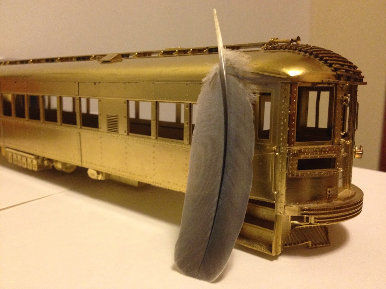
The North Shore car arrived last week. Here it is!

Despite its flaws—including a bent pilot—I'm quite satisfied. After reviewing the CERA bulletins, I've determined that this is a model of the 737-776 series of cars as modernized, but not as a Silverliner. These cars were actually from two separate series built by two different manufacturers at different times, but having almost identical specifications. 737-751 were built by Pullman in 1928. The rest were produced by Standard in 1930. I haven't picked a series yet (although I'm leaning toward the Standard-built cars) but I do know that I will not be giving it the number of a preserved car. I like the concept of recreating and preserving (in a small way—no pun intended) something that was lost.

The car is missing a few things. This includes (but is not limited to) trucks, couplers, poles, and trolley hooks. Also, on one corner a small bracket seems to have been knocked off. I believe this is supposed to hold either flags or lanterns. The more learned will have to comment.

The hole is where the missing bracket is supposed to be.

A little known fact about these cars is that while being modernized, the trucks and poles were removed. The cars were then painted in a rather striking all-brass livery. The area around the shops was also home to an American species of roc that was long believed to have been mythical. (The "legend" of these giant birds were the inspiration for Baby Huey.) The birds have since gone extinct, but I have managed to locate a rare color photograph depicting this situation. The Smithsonian will no doubt be interested in my finding.

Sunday, September 21, 2014

Success on Two Fronts

Okay, so this update is long overdue. In the intervening weeks I have had some successes with my models and my "layout." I have come to the decision (largely in part because of the purchase of the 2000-series cars) that the Dunsel Line will not be a traditional trolley layout. It will be a two-rail layout equipped with dummy third rail. This will allow operation of CA&E, North Shore, and "L" equipment even if the cars (such as the 2000s) are not equipped with trolley poles or pantographs. This will necessitate the pole- or pan-equipped cars to built to accommodate two modes of running, as they should be. This does come with a downside.

Prototypical placement of the third rail on the "L" has the top of the third rail 6½ inches above the top of the running rail and 20-1/8 inches from the inside edge of the running rail to the center line of the third rail. Contact with the third rail is made by a metal shoe (or a paddle in the case of very early AE&C cars). Contact with the third rail is made by gravity: the shoe naturally hangs and then glides across the surface of the rail when present. The problem here is that most on models, the shoe has been made in the free hanging or "down" position. This is fine for trolley operation as when under wire, the shoes should hang freely. With prototypical third rail placement, the shoe now hangs too low for operation. The MTH "L" cars have the shoe in the up or "on rail" position. This works well for prototypical placement unless the third rail is on the non visible side of the model or at gaps. In these situations the shoe isn't hanging when it should be.

A trolley beam on a St. Petersburg 2000-series car. The shoe is depicted as hanging free. This would collide with a prototypically placed third rail.

MTH made the shoe in the "on rail" position.

There are three ways to work this problem. The first is to use the commercially available trolley beams in the free hanging position and adapt the height of the third rail accordingly. The other is to use the on rail position and place the third rail according to where it will be seen by the viewer. I'm not entirely satisfied by either of these options.

The third option is, if at all possible, is to create a trolley beam with a third rail shoe that functions like the prototype so that it can glide or dangle as need be. I'm a neurotic freak so this sounds extremely satisfying. I had this idea in the past, but dismissed it due to my inability to construct such a small thing effectively. But now I can have things 3D printed! And according to the specifications on Shapeways' site, many materials do allow for moving parts if proper clearance is built into the design. Looks like I've got a new project...

Granted, this won't take into account the placement in the third rail given the difference in scales (1/48 vs. the 1/45 for the MTH cars) but I'll just have to live with it.

This actually leads to the first of my successes. The prototype seat for the 3200-series cars arrived from Shapeways on Monday and I’m pleased with the results.

This took far longer than I’d expected and was also fraught with no small amount of frustration. The first problem was getting the angle of the seat back to my own satisfaction (picture a weirdo riding the Ravenswood messing around with perfectly normal seats with a protractor and a crude, improvised plumb bob). The next (and far more frustrating) bit was to create the handhold on the back of the seat.

I was very much relieved to discover that the handholds on the 3200s are much simpler than their counterparts on the 22-, 24-, and 2600-series cars. Until I tried to produce them, that is. The process involves making an appropriately sized circle which will be the “pipe” in question and then drawing a curved line representing the path of the pipe. In this case, the path went up from the circle, curved to one side, continued horizontally, and then curved down to the same height at which it started. Once that path is created and placed on the appropriate plane (another interesting quest in of itself) and positioned with the start at the center of the circle, the “follow me tool” is used to extrude the circle along the specified path. Simple. Or not, as I kept getting error messages that people in Youtube videos never seemed to get.

Once I realized that the problem was that some combination of Google Sketchup and my computer was being a lazy pile of rancid horse turds, the project moved along swiftly. (No Skokie pun intended.) My problem was that I was trying to create the curve in 1/45 scale. This was simply too small for the program to handle. It wouldn’t do the math. However, once I scaled up the curve/circle combination to a large enough size, I was blessed with numerous beautiful curved pipe segments. Armed with this, I used the scale tool to reduce the piece to the appropriate size, and voila! (Apparently Sketchup has no problem rendering such a small thing, it just doesn’t want to draw it.)

Once that hurdle was cleared, I saved my file, exported it as a .dae (which is a file type native to Sketchup 8 and can be read by Shapeways) and sent the .dae off to be printed. And like that, it was done.

The question I keep getting asked when I’ve shown this thing around is, why did you only make one? I wanted to produce one seat just to determine what the end product would look like on a simple design and then rework my design from there. A single transverse seat seemed like the best option. This was printed in “Frosted Ultra Detail.” There are other (cheaper) alternatives available, however none of the other materials were sufficient to produce the detail included and wouldn’t pass some of the initial checks.

There was a slight (and I do mean slight) problem in the printing process. I didn’t include the stanchion that connects to the handhold on the back of the seat, but I did include the connection for it. This is the little nodule in the corner. This is an object that is shaped almost like an inverted, blunted, ogive cone. It is quite diminutive, but still bigger in diameter than the bar itself. The problem is that it didn’t print fully. There’s a “gap” in the back. Fortunately, it is so tiny that it isn’t very noticeable.

Now that I’ve seen what it looks like, I can say I like it and I can go ahead and make up the other variants. (Assuming I don’t go back and try to add the curves to the seat back and “cushion.”)

This still leaves the problem of the stanchions themselves. Still haven’t figured that one out just yet.

The second success is that the Dunsel Line has acquired a new piece of rolling stock! I am still waiting for it to arrive, but it is a high numbered 700 North Shore Line car in brass. (My knowledge of the North Shore isn’t what it should be, so I can’t identify the specific series until I consult my father’s CERA bulletins.)

This is my first North Shore model. The model didn’t come with trucks, trolley poles, or even a box. (This is why I it wasn’t identified when I purchased it.) What it does have is a few dents on the roof and some tarnish in a few spots, but these things should be easily fixed.

The plan here is to paint it in the final variant of the North Shore’s green and red and equip it with appropriate Q Car Company trucks insulated for two rail operation. Power will be supplied by a pair of NWSL Magic Carpets. A selector switch will, of course, have to be installed for two rail or trolley power. Poles will also be Q Car.

Exciting times ahead!